
Dual span absolute pressure sense die

a technology of absolute pressure and die, applied in the field of sensor methods and systems, can solve the problems of changing the output voltage of the sensor, the sensor cannot capture the high frequency pressure pulsation, and the likely to provide less than optimal, etc., and achieves accurate measurement, small voltage, and greater pressure

Inactive Publication Date: 2009-03-17
HONEYWELL INT INC
View PDF13 Cites 91 Cited by
  • Summary
  • Abstract
  • Description
  • Claims
  • Application Information

AI Technical Summary

Benefits of technology

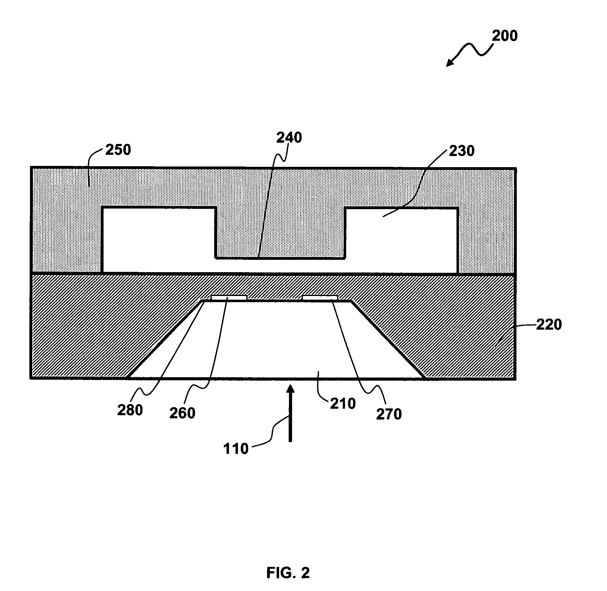
The present invention provides improved sensor methods and systems, particularly pressure sensors. The invention includes an absolute pressure sensor with a unique design that allows for accurate measurement of low and high pressures without using a linear scale. The sensor includes a sense die with a reference chamber and a beam that limits the movement of the diaphragm. The sensor also includes four piezoresistors buried in a thin silicon diaphragm, which allows for accurate sensing of pressure changes. The invention provides improved accuracy and reliability in pressure sensing applications.

Problems solved by technology

The resistance in the arms of the bridge changes by an amount proportionate to applied pressure, which can resulting in a change to the sensor output voltage.
One problem with the type of pressure sensors and mean value type of measuring utilized in EGR systems is that such sensors do not capture the high frequency pressure pulsations originating from the opening and closing of the exhaust and inlet valves.
The pressure sensor, which is typically located after the poppet valve, is likely to provide less than optimal results due to turbulence that occurs after the valve and the poor physical location of the pressure sensor.
The pressure reported from such a sensor is typically lower than the pressure in the intake manifold in many operating conditions, thus indicating a pressure increase over the EGR coolers, which is physically impossible.

Method used


Image

  • Dual span absolute pressure sense die
  • Dual span absolute pressure sense die
  • Dual span absolute pressure sense die

Examples


Embodiment Construction

[0017]The particular values and configurations discussed in these non-limiting examples can be varied and are cited merely to illustrate at least one embodiment and are not intended to limit the scope thereof.

[0018]An exhaust back pressure sensor using absolute micro-machined pressure sense die is disclosed herein. In such a device, an absolute pressure sensor with high isolation between the sensed media and the sensor electronics can be implemented. Such a sensor can be utilized, for example, to sense the exhaust pressure in automotive engines.

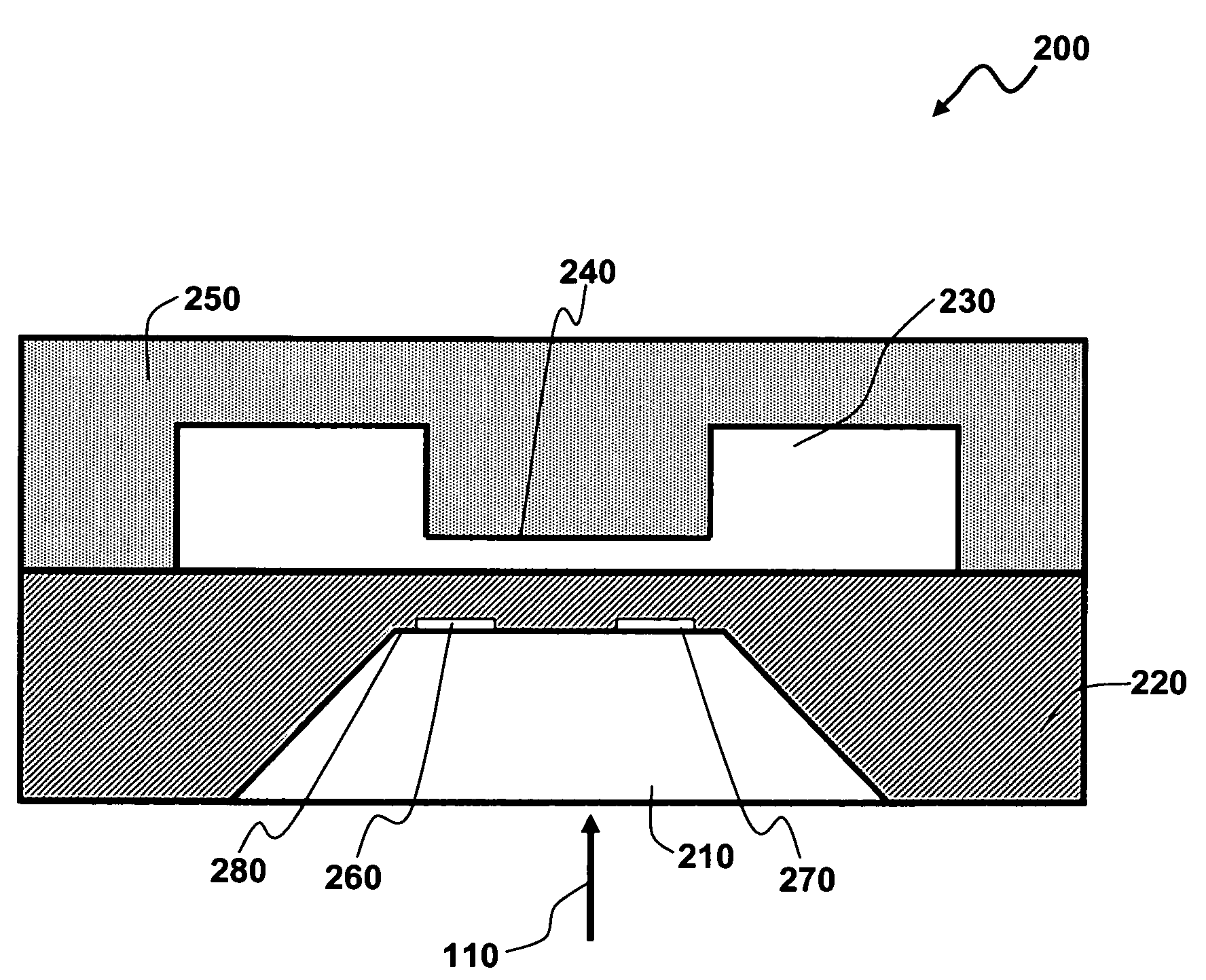
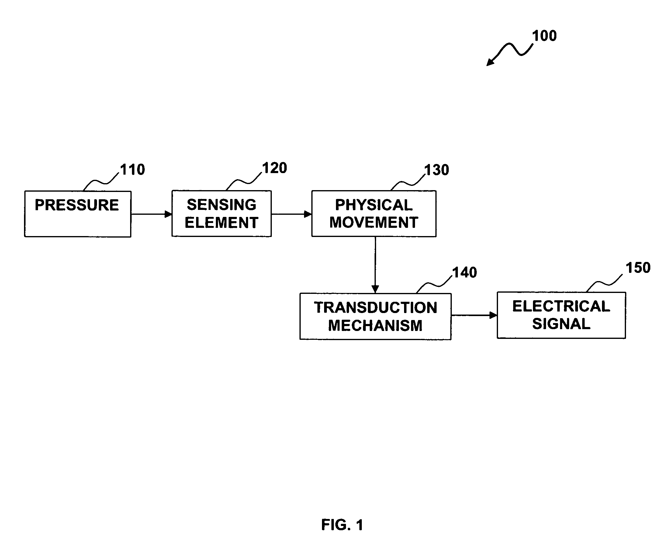
[0019]Referring to FIG. 1, a block diagram depicting the functioning of an absolute pressure sensor system 100 is illustrated, in accordance with a preferred embodiment. Note that in FIGS. 1-3, identical or analogous parts or elements are generally indicated by identical reference numerals. System 100 generally includes a transduction mechanism 140 that generates an electrical signal 150. System 100 further includes one or more sensing elemen...


PUM

PropertyMeasurementUnit
pressuresaaaaaaaaaa
pressureaaaaaaaaaa
distanceaaaaaaaaaa

Abstract

An absolute pressure sensor includes a sense die with a reference chamber on a top side thereof. The reference chamber comprises a precisely fabricated beam that limits the travel of a diaphragm. The beam can be positioned in a cap or cover member of the sense die, thereby allowing the sense die diaphragm to move freely for a particular distance. Over this distance, the sense die will have one sensitivity. When the sense die is pressurized to a certain point, the diaphragm moves until it contacts the beam member in the cap or cover. When the diaphragm hits the beam, the sensitivity of the sense die changes, thereby allowing a smaller voltage out for the greater pressure in. Such an arrangement permits the sensor to provide a function that accurately measures low pressure and measures a higher pressure without utilizing a linear scale.

Description

TECHNICAL FIELD[0001]Embodiments are generally related to sensor methods and systems. Embodiments are also related to pressure sensors. Embodiments are additionally related to exhaust back pressure sensors. Embodiments are also related to absolute pressure sensors that include dual span sense die.BACKGROUND OF THE INVENTION[0002]Pressure metrology is the technology of transducing pressure into an electrical quantity. Normally, a diaphragm construction is used with strain gauges either bonded to, or diffused into it, acting as resistive elements. Under the pressure-induced strain, the resistive value changes. Many micromachined absolute pressure sensors function by mounting the material removal side of a silicon sense die into glass. Such a methodology can create an absolute pressure sensor. In general, absolute pressure sensor can employ a sealed volume of gas or vacuum on one side of a diaphragm, with another side of a diaphragm being exposed to a sensed fluid.[0003]Some pressure s...

Claims


Application Information

Patent Timeline
Patent Type & Authority Patents(United States)
IPC IPC(8): G01L9/06
CPCG01L9/0051G01L15/00
Inventor WADE, RICHARD A.
Owner HONEYWELL INT INC
Learn More