Delay variation buffer control technique

a delay variation and buffer control technology, applied in the field of controllers for delay variation buffers, can solve the problems of inability to achieve proper cell delay variation control and failure to successfully perform delay variation control, so as to improve management and maintenance, avoid network management burden, and achieve rapid maintenance work

Inactive Publication Date: 2006-06-06
JUMIPER NETWORKS INC
View PDF11 Cites 4 Cited by
  • Summary
  • Abstract
  • Description
  • Claims
  • Application Information

AI Technical Summary

Benefits of technology

[0020]As described above, according to the present invention, a variation buffer value can be rapidly corrected to a proper value without any test prior to actual data communication. Therefore, efficient data communication can be achieved reflecting the actual network operation status.
[0021]In the case where no cell delay variation is detected, the variation buffer value is initialized to the basic value and thereby ATM cells stored in the buffer are read out at intervals of a shorter time period. Since undesired delay of transfer of ATM cells stored in the buffer can be avoided, the variation buffer control is suitable for data communications requiring real-time operation.
[0022]Further, since the network management side can know on the correction of variation buffer value by receiving the autonomous message, the capability of management and maintenance can be improved without burden on the network management side.
[0023]Further, when the number of contiguous occurrences of cell delay variation exceeds the predetermined value, an autonomous message of over-frequency of delay variation occurrence is sent to the network management side and the buffer value is not updated. Therefore, rapid maintenance work can be achieved without burden on the network management side.

Problems solved by technology

In other words, a delay-variation control cannot be successfully performed unless ATM cells are permitted to be discarded.
However, this prior art needs to measure the amount of cell variation by sending test cells before actual data transmission.
Therefore, the detected cell delay variation does not reflect an actual network operation status, which cannot achieve proper cell delay variation control.

Method used


Image

  • Delay variation buffer control technique
  • Delay variation buffer control technique
  • Delay variation buffer control technique

Examples


Embodiment Construction

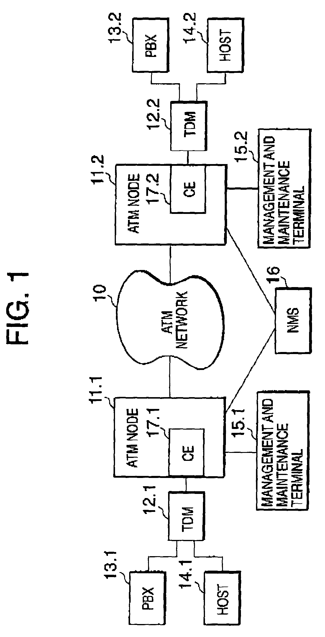
[0031]Referring to FIG. 1, it is assumed for simplicity that a network system is composed of STM networks connected via an ATM network 10. The network is realized by shifting an existing dedicated network using a time-division multiplexer (hereafter, abbreviated as TDM) to ATM network such that the existing TDM is accommodated under the ATM network.

[0032]More specifically, ATM nodes 11.1 and 11.2 are connected via the ATM network 10. The ATM node 11.1 is connected to an existing TDM 12.1 that is in turn connected to PBX (Private Branch eXchange) 13.1 and a host computer 14.1. Similarly, the ATM node 11.2 is connected to an existing TDM 12.2 that is in turn connected to PBX 13.2 and a host computer 14.2. The respective PBXs 13.1 and 13.2 may accommodate local networks (not shown). Synchronous communications using STM frames are performed in the host computer 14.1 and the local network accommodated in the PBX 13.1 and in the host computer 14.2 and the local network accommodated in the...


PUM


Abstract

A delay variation buffer controller allowing proper cell delay variation control reflecting an actual network operation status is disclosed. A detector detects an empty status of the data buffer when data is read out from the data buffer at intervals of a controllable time period. A counter counts the number of contiguous times the empty status was detected. A proper time period is calculated depending on a value of the counter at a time when the empty status is not detected and the value of the counter is not zero. A timing corrector corrects the controllable time period to match the proper time delay and setting the controllable time delay to a predetermined value when the empty status is not detected and the value of the counter is zero.

Description

BACKGROUND OF THE INVENTION[0001]1. Field of the Invention[0002]The present invention relates to a controller for a delay variation buffer, and in particular to a controller and control method suitable for a delay-variation buffer absorbing delay variation of cells received from ATM (asynchronous transfer mode) network and transferred to STM (synchronous transfer mode) network.[0003]2. Description of the Related Art[0004]In a network composed of an ATM network connecting two STM networks that both uses existing network equipment to transfer data in a period of constant frame, a circuit emulation service is needed at an interface between ATM and STM networks to perform bi-directional conversion between ATM cell and STM frame. A circuit emulator providing the circuit emulation service (hereafter, abbreviated as CE) is implemented by emulating STM on ATM line.[0005]Since ATM cells may be transferred through different paths across an ATM network, variations in delay or jitter occur to c...

Claims


Application Information

Patent Timeline
Patent Type & Authority Patents(United States)
IPC IPC(8): H04L12/28H04J3/06H04L47/22H04L49/9023H04Q11/04
CPCH04J3/0632H04Q11/0478H04L2012/5654H04L2012/5649
Inventor ITAI, TAIHEI
Owner JUMIPER NETWORKS INC
Why Eureka
Try Eureka