
Constant velocity joint boot

Active Publication Date: 2006-06-06
TOYODA GOSEI CO LTD
View PDF12 Cites 12 Cited by
  • Summary
  • Abstract
  • Description
  • Claims
  • Application Information

AI Technical Summary

Benefits of technology

[0012]In view of such circumstances, an object of the present invention is to provide a boot in which shrinkage is prevented from being generated at the thick-walled portion of the larger cylindrical portion and uniform fastening is achieved when fastened by the fastening member so that required sealing property can be achieved.

Problems solved by technology

However, it is difficult to form the larger cylindrical portion constituting of the thick-walled portion and the thin-walled portion by blow molding.
However, in this case, two forming processes are required, which is disadvantageous in that a large number of processes are required.
However, when forming the larger cylindrical portion constructed of the thick-walled portion and the thin-walled portion by injection molding, there may be the case in which surface sink is generated at the thick-walled portion after molding, and consequently, a gap is formed with respect to the mating member when fastened.
Consequently, it may result in a defective good, which may lead to leakage of grease.
However, in the boot of this kind, there is a problem in that the strength of the rib is tend to be insufficient, and thus sealing property required for deforming the ribs when being fasten by the fastening member cannot be obtained.
However, in the boot of this kind, since the thick-walled portion is deformed so that the width of the slit is narrowed when being fastened by the fastening member and thus defection is constantly generated, further deflection may occur due to bending of the bellows portion when in use, and thus it may suffer some cracks.
In such a case, an uniform fastening force cannot be obtained and thus required sealing property cannot be obtained.
However, in this boot, there is a problem in that stress varying points are generated at both ends of the slit when fastened by the fastening member and thus uniform fastening force cannot be obtained, whereby required sealing property cannot be achieved.

Method used


Image

  • Constant velocity joint boot
  • Constant velocity joint boot
  • Constant velocity joint boot

Examples


Embodiment Construction

[0032]The present invention will be described in detail below based on an experimental example.

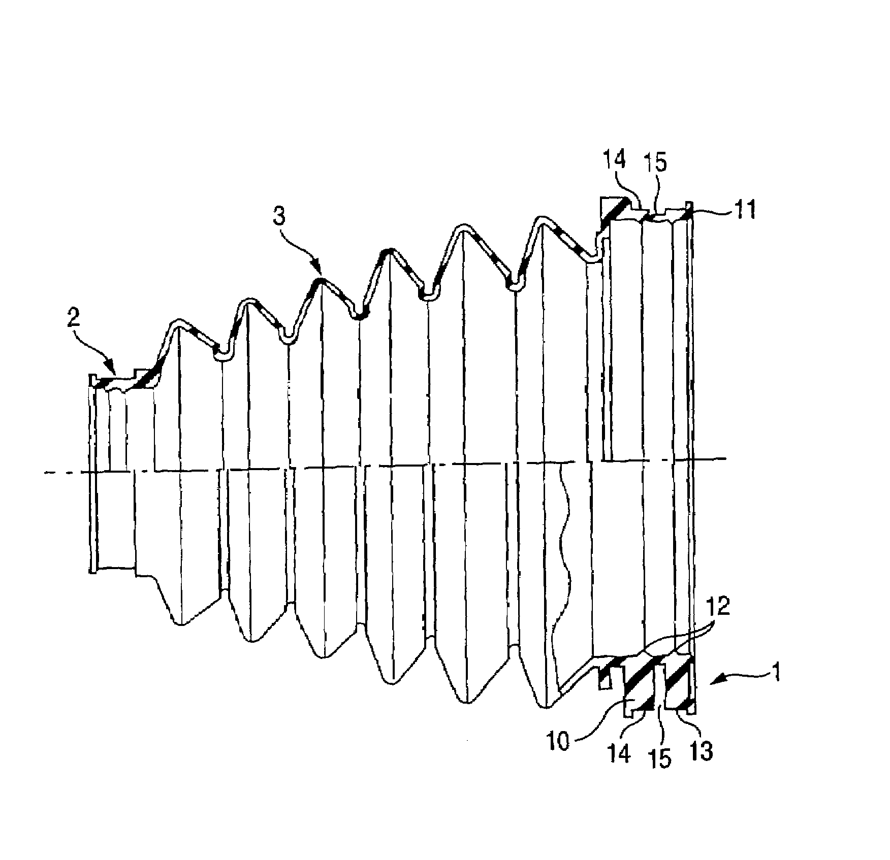
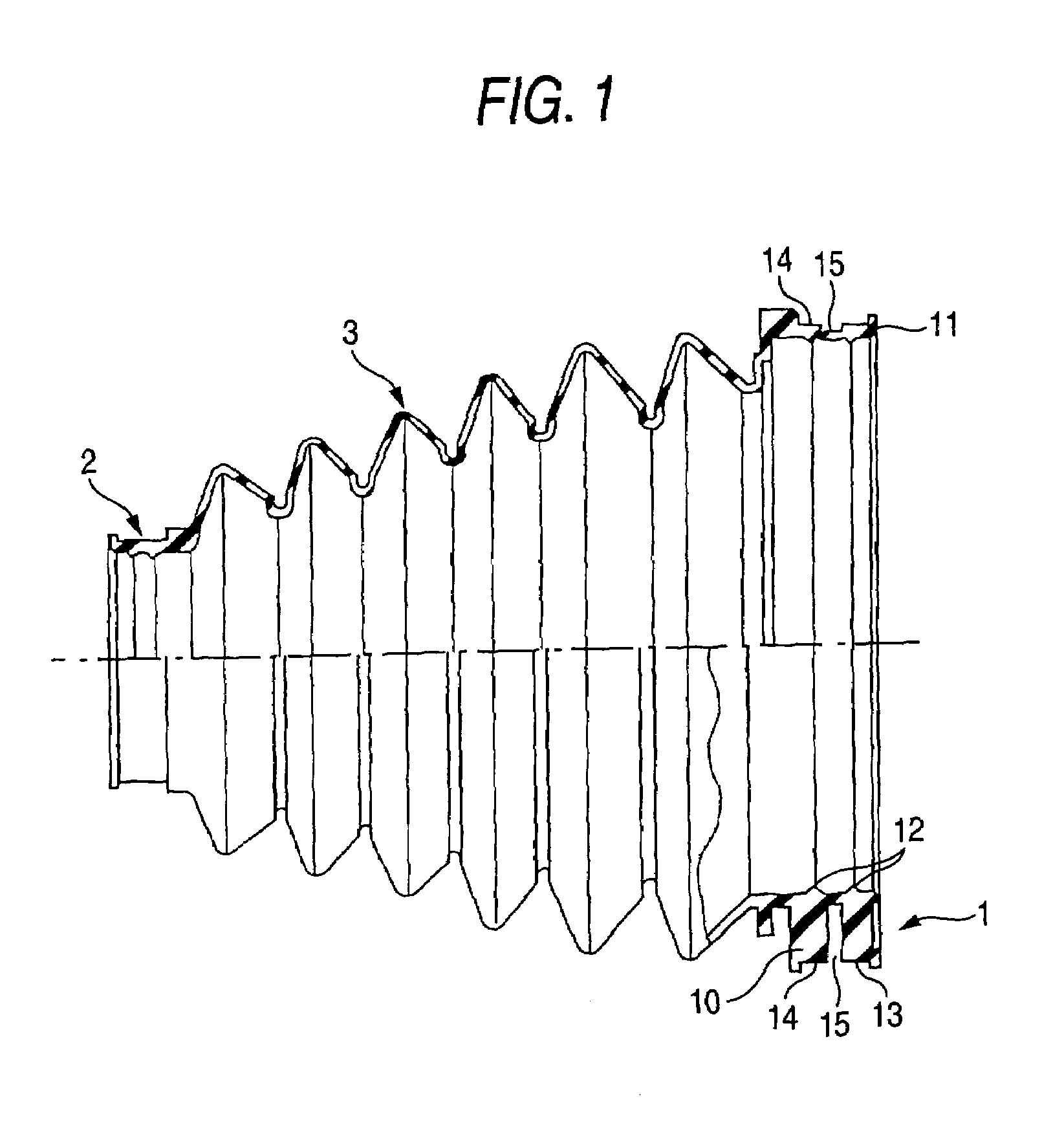
[0033]FIG. 1 is a front view of a constant velocity joint boot according to the present invention showing a cross section of the half body thereof, and FIG. 2 is a side view of FIG. 1 viewed from the side of the larger cylindrical portion. The constant velocity joint boot is constructed of a larger cylindrical portion 1, a smaller cylindrical portion 2 having a smaller diameter than the larger cylindrical portion 1, and a bellows portion 3 of substantially truncated conical shape for integrally connecting the larger cylindrical portion 1 and the smaller cylindrical portion 2. The bellows portion 3 is formed of thermoplastic elastomer by blow molding, and the larger cylindrical portion 1 and the smaller cylindrical portion 2 are formed of thermoplastic elastomer integrally with the bellows portion 3 by injection molding.

[0034]In this boot, the larger cylindrical portion 1 is fastened to a m...


PUM


Abstract

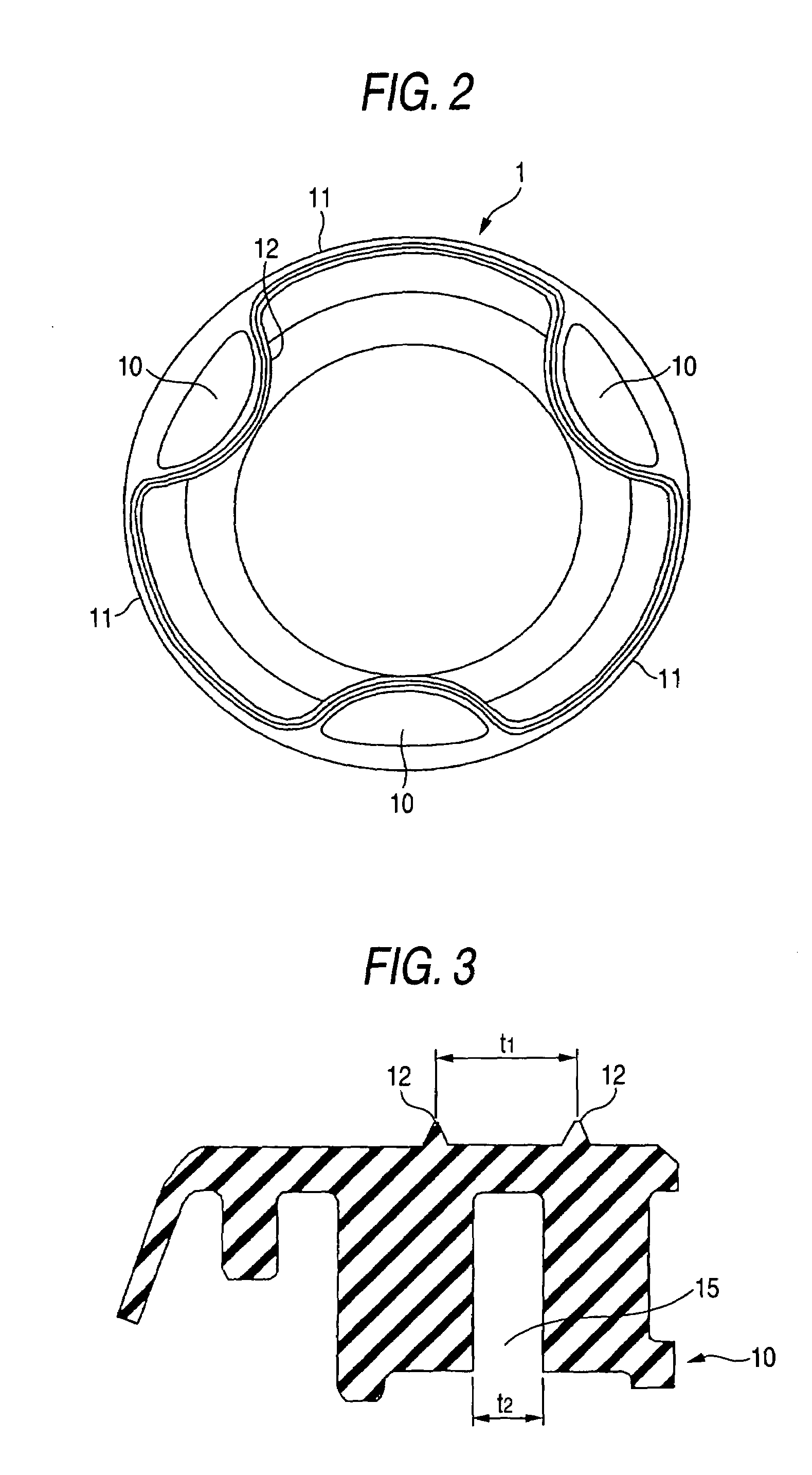
In a boot including a larger cylindrical portion having a thick-walled portion and a thin-walled portion continuing smoothly in the circumferential direction on the inner peripheral surface, a ring groove coming full circle on the outer peripheral surface of the larger cylindrical portion is formed.Since shrinkage at the thick-walled portion can be prevented by the ring groove, and the ring groove is formed smoothly over the entire thick-walled portion and the thin-walled portion, there exists no varying point at which a stress generated when fastening with a fastening member suddenly changes.

Description

[0001]The present application is based on Japanese Patent Application No. 2002-304099, the entire contents of which are incorporated herein by reference.BACKGROUND OF THE INVENTION[0002]1. Field of the Invention[0003]The present invention relates to a boot covered by a constant velocity joint that is indispensable for a joint for a drive shaft of a front-wheel-drive vehicle for protecting a joint portion of the constant velocity joint from invasion of water or dust.[0004]2. Related Art[0005]Hitherto, a joint portion of a constant velocity joint is covered by an accordion-folded boot and thus smooth rotation thereof at large angle is maintained by preventing invasion of water or dust. The constant velocity joint boot is constructed of a larger cylindrical portion of a large diameter to be held by a mating member such as a joint outer lace, a smaller cylindrical portion of a smaller diameter than the larger cylindrical portion held by a shaft, and a bellows portion in the shape of sub...

Claims


Application Information

Patent Timeline
IPC IPC(8): F16C1/26F16D3/84F16J3/04F16J15/52
CPCF16J3/042F16D3/845
Inventor TORIUMI, MAYUKIFURUTA, YUJIMORI, YOSHIKAZU
Owner TOYODA GOSEI CO LTD
Learn More