
Shim plate

Active Publication Date: 2018-05-31
LG CHEM LTD
View PDF18 Cites 0 Cited by
  • Summary
  • Abstract
  • Description
  • Claims
  • Application Information

AI Technical Summary

Benefits of technology

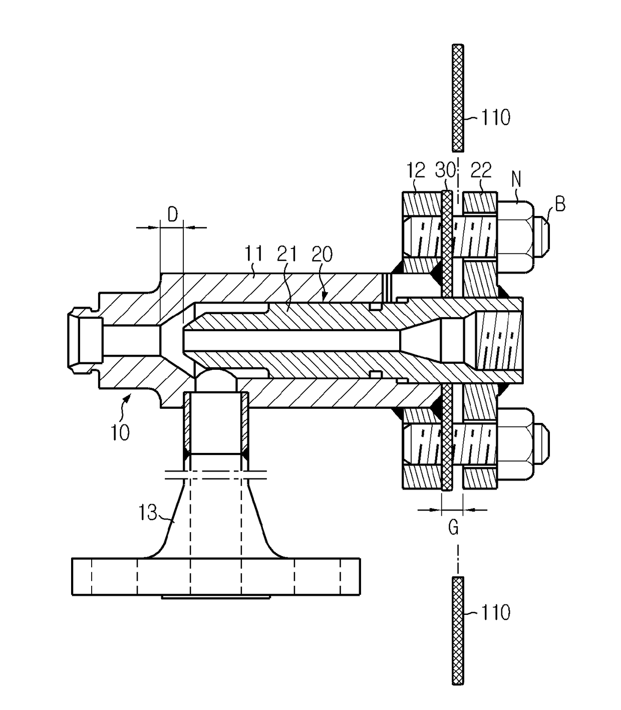
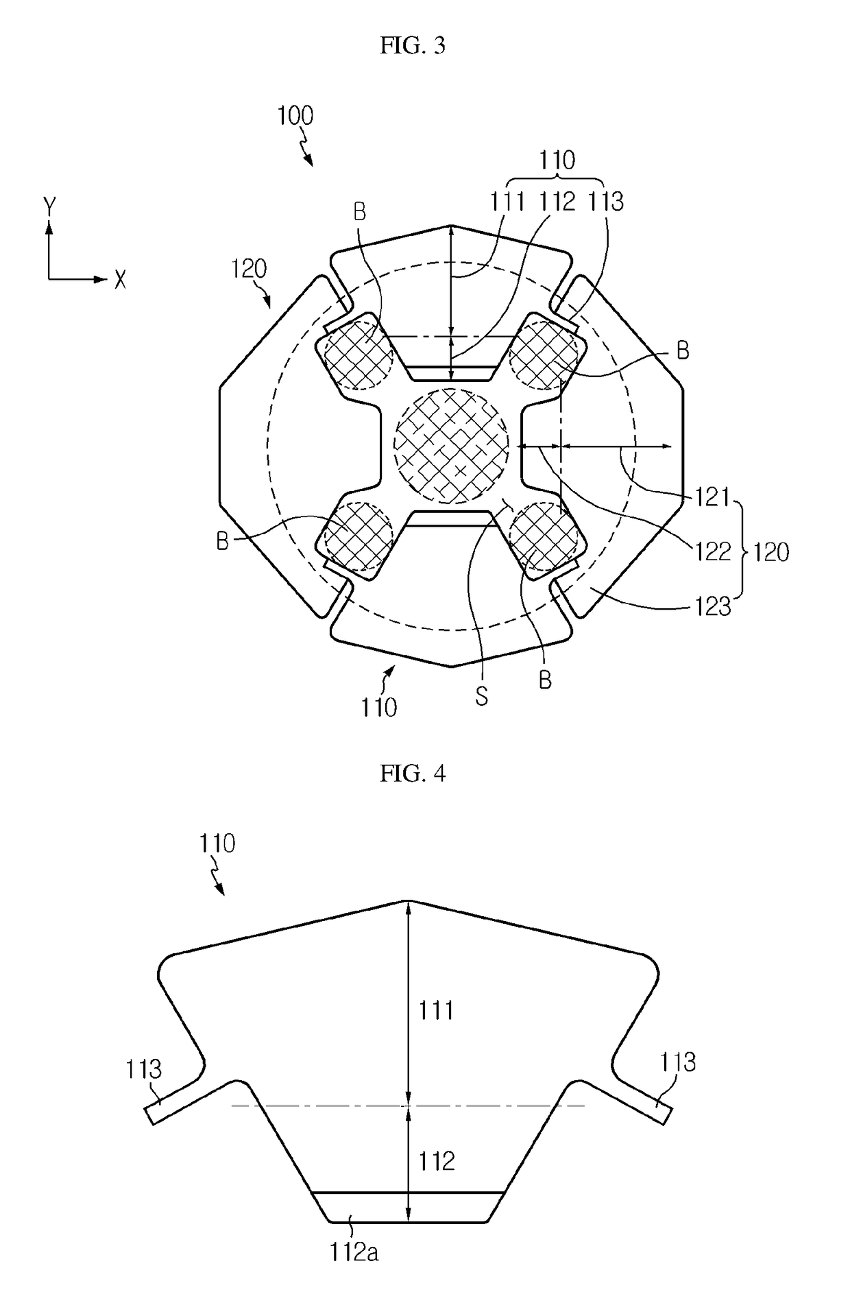
[0023]In an aspect of the present disclosure, a plurality of separable plate pieces may be inserted into a gap between assembly components in a lateral direction, and thus, replacement or addi

Problems solved by technology

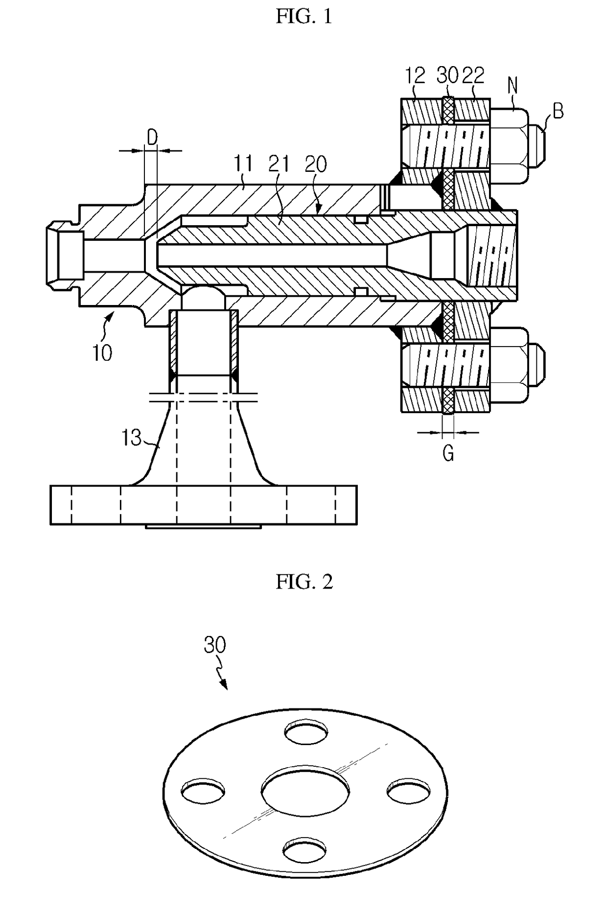
However, as illustrated in FIG. 2, the shim plate 30 according to the related art cannot be used unless a nut N is loosened from the flanges 12 and 22 and all of four shafts B are removed and then the polymer nozzle part 20 is completely separated from the st

Method used


Image

  • Shim plate
  • Shim plate
  • Shim plate

Examples


Example

BEST MODE

[0033]Hereinafter, preferred embodiments of the present disclosure will be described in detail with reference to the accompanying drawings. Prior to the description, it should be understood that the terms used in the specification and the appended claims should not be construed as limited to general and dictionary meanings, but interpreted based on the meanings and concepts corresponding to technical aspects of the present disclosure on the basis of the principle that the inventor is allowed to define terms appropriately for the best explanation.

[0034]Therefore, the embodiments described and the drawings illustrated in the present specification are just a preferable example for the purpose of illustrations only, not intended to limit the scope of the disclosure, so it should be understood that other equivalents and modifications could be made thereto at the time of filing the present application without departing from the scope of the disclosure.

[0035]The embodiments of the...


PUM


Abstract

According to an aspect of the present disclosure, a shim plate which is inserted between components that are assembled to and disassembled from one another via at least one shaft may be provided. The shim plate includes a plurality of plate pieces that are separable from one another, wherein the plurality of plate pieces are configured such that one plate piece is connected to the other plate piece in a circumferential direction, and an internal ring-shaped empty space is formed.

Description

TECHNICAL FIELD[0001]The present disclosure relates to a shim plate, and more particularly, to a shim plate for easily adjusting distances between components of an assembly device.[0002]The present application claims priority to Korean Patent Application No. 10-2015-0108285 filed on Jul. 30, 2015 in the Republic of Korea, the disclosure of which is incorporated herein by reference.BACKGROUND ART[0003]In general, in installation, operation and repair of industrial equipment such as a pump or a motor, an atomizer or a fan, a fixed bolt is used in axis alignment, and a shim plate is used to adjust a height of the fixed bolt.[0004]The shim plate is a thin plate that is placed or inserted in order to adjust a height or a gap during axis alignment, and may be formed of a copper plate, an iron plate or paper.[0005]FIG. 1 is a schematic cross-sectional view of an atomizer to which a shim plate according to the related art is applied, and FIG. 2 is a perspective view of the shim plate of FIG...

Claims


Application Information

Patent Timeline
IPC IPC(8): F16B43/00F16S1/00
CPCF16B43/00F16S1/00F16B43/007
Inventor JEON, JAE-HYOUNGJO, YANG-BAEPARK, WON-CHAN
Owner LG CHEM LTD
Learn More