
Method and system for estimating the position of a movable device in a borehole

a technology of moving devices and boreholes, applied in the field of methods and systems for estimating the position of moving devices in boreholes, can solve problems such as double integration, inaccurate models of elasticity and friction, and various types of errors in approaches. to achieve the effect of improving the accuracy of downhole position measurements

Inactive Publication Date: 2006-06-06
SCHLUMBERGER TECH CORP
View PDF14 Cites 42 Cited by
  • Summary
  • Abstract
  • Description
  • Claims
  • Application Information

AI Technical Summary

Benefits of technology

[0015]An object of the present invention is to evaluate and preferably to improve the accuracy of downhole position measurements.
[0026]The present invention provides a convenient platform for combining, in the calculation of the location probability distribution, measurements which may derive from disparate sources but which can carry useful information concerning the repositioning of the device. This combination is advantageous because the range of likely positions for the device, as defined by the location probability distribution, is itself likely to be narrower when the amount of information used to calculate the probability distribution is increased.
[0030]A particular advantage of the approach is that it permits the combination of evidence from multiple sensors (including odometers) to yield more accurate depth estimates than are possible with a single sensor or technique. Error from odometers grows with distance, but detection of landmarks reduces error spread again. For example, it was found that by applying the present invention to measurements from odometers, CCLs and gamma ray sensors together, the error can be kept to within 20 centimeters over a distance of several kilometers. In contrast, dead-reckoning errors could be tens or hundreds of metres over this distance.

Problems solved by technology

However, all of these approaches are subject to various types of error: wheels with odometers may slip, coiled tubing has a tendency to coil in the borehole, double integration magnifies errors, models of elasticity and friction may not be accurate.
Because of this, when using dead-reckoning the magnitude of the error tends to increase with distance travelled.
However, a CCL may occasionally fail to detect an adjacent casing collar, or may spuriously detect a non-existent collar, due to noise.
Because the sensors are usually not able to distinguish between different casing collars, this results in uncertainty in position.
However, map-matching can affected by sensor noise, as well as suffering from drawbacks similar to those associated with landmark recognition.

Method used


Image

  • Method and system for estimating the position of a movable device in a borehole
  • Method and system for estimating the position of a movable device in a borehole
  • Method and system for estimating the position of a movable device in a borehole

Examples


example

[0061]We have applied the above theory to the example of a downhole autonomous robot. Dead reckoning information is obtainable from an odometer fitted to the robot's wheels. This is liable to errors due to slippage, and the conditional PDF, P(d|a,d0), may be used to model the effect of attempting to move the distance registered by the odometer. Alternatively, inertial navigation may be used, with its own error sources and stochastic model of P(d|a,d0).

[0062]Some landmark information is obtainable from a CCL that detects casing joints in a cased hole. Other landmark detection schemes may also be employed, such as detecting the presence of casing perforations. For each landmark, we can devise a mathematical model that gives the probability of detecting the landmark from an arbitrary position, P(o|d).

[0063]Map-matching information can come from the increase in pressure and temperature with depth, and from any other suitable logging sensor (such as a gamma-ray sensor). Less precise map ...


PUM


Abstract

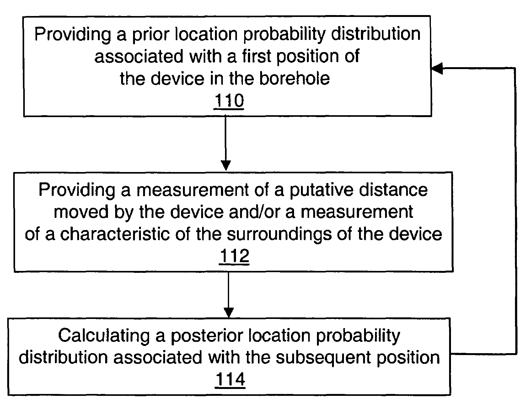
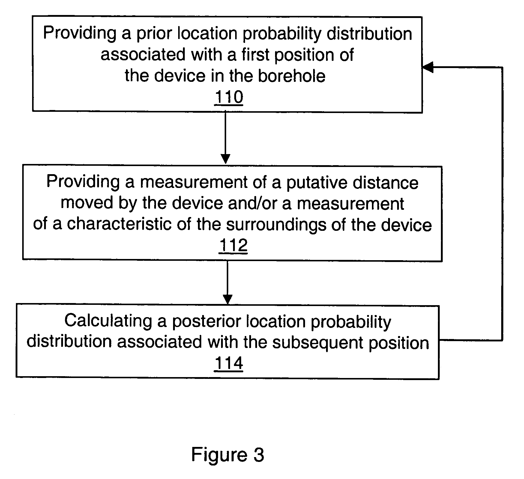
A method is provided for estimating the position of a movable device in a borehole. The method comprises the steps of:(a) providing a prior location probability distribution associated with a first position of the device in the borehole,(b) providing a measurement of a putative distance moved by the device and / or a measurement of a characteristic of the surroundings of the device, the or each measurement being associated with movement of the device to a subsequent position in the borehole, and(c) calculating a posterior location probability distribution associated with the subsequent position, the posterior location probability distribution being conditional on the prior location probability distribution, and the or each measurement.

Description

FIELD OF THE INVENTION[0001]This invention relates to a method and system for estimating the position of a movable device in a borehole.BACKGROUND OF THE INVENTION[0002]There are a number of situations in which it is desirable to be able to estimate accurately position in a hydrocarbon well borehole. For example:[0003]when making a wireline log or analysing a slickline log, the position of the logging tool is needed when each measurement is made;[0004]when intervening in a well with coiled tubing, the position of the tool at the end of the tubing is required;[0005]when drilling, the location of the bottom hole assembly (BHA) and bit is needed; and[0006]when inserting an autonomous device (e.g. of the type disclosed in U.S. Pat. No. 6,405,798) into a well, the device should be able to determine its own position for navigation.[0007]For each of these situations, application-specific dead-reckoning approaches to estimate position may be adopted. For example, one approach is to measure ...

Claims


Application Information

Patent Timeline
IPC IPC(8): E21B47/09E21B47/04
CPCE21B47/09E21B47/04
Inventor BARROW, HARRY
Owner SCHLUMBERGER TECH CORP
Learn More