Inverter control method and its device

Inactive Publication Date: 2006-05-30
DAIKIN IND LTD +4
View PDF10 Cites 40 Cited by
  • Summary
  • Abstract
  • Description
  • Claims
  • Application Information

AI Technical Summary

Benefits of technology

[0056]When the inverter controlling method according to an aspect of the present invention is employed, the method includes a single-phase rectification circuitry and three-phase inverter, determines a capacitance of a capacitor so as to greatly pulsate an output voltage from the single-phase rectification circuitry at twice frequency of a power frequency, which capacitance is connected between output terminals of the single-phase rectification circuitry, and carries out controlling for suppressing the current flowing into the capacitor from the power source through the single-phase rectification circuitry when the three-phase inverter is controlled so as to supply output voltage or output current from the three-phase inverter to a motor. Therefore, harmonics in the power current can be reduced.
[0070]When the inverter controlling apparatus of claim 13 is employed, controlling means including phase determination means for determining a phase of the current for torque to be a phase of delay is employed as the controlling means. Therefore, compensation of the capacitor current can be carried out easily, and operations and effects similar to those of claim 7 are realized.

Problems solved by technology

In this case, disadvantages arise such that a power factor in power side is lowered, and harmonics are increased.
Therefore, disadvantages arise such that a size becomes greater following the employment of those elements, and increase in cost is realized.
Therefore, further increase in cost is realized.
Therefore, disadvantages arise such that a lifetime of an inverter circuitry including a diode-bridge circuitry becomes shorter due to a short lifetime of an electrolytic capacitor, and usage environment of an inverter circuitry including a diode-bridge circuitry is limited due to thermal characteristics of an electrolytic capacitor.
Therefore, disadvantages arise such that increase in cost, and increase in entire size of the inverter device.
Therefore, it becomes very difficult that the inverter circuitry of FIG. 20 is employed in home electric devices.
Disadvantage arises that harmonics of the power current (input current) i1 cannot be controlled to be smaller (in ideal, cannot be controlled to be a sine wave) when the capacitor current is not compensated.

Method used


Image

  • Inverter control method and its device
  • Inverter control method and its device
  • Inverter control method and its device

Examples


Embodiment Construction

[0096]Hereinafter, referring to the attached drawings, we explain embodiments of an inverter controlling method and apparatus according to the present invention, in detail.

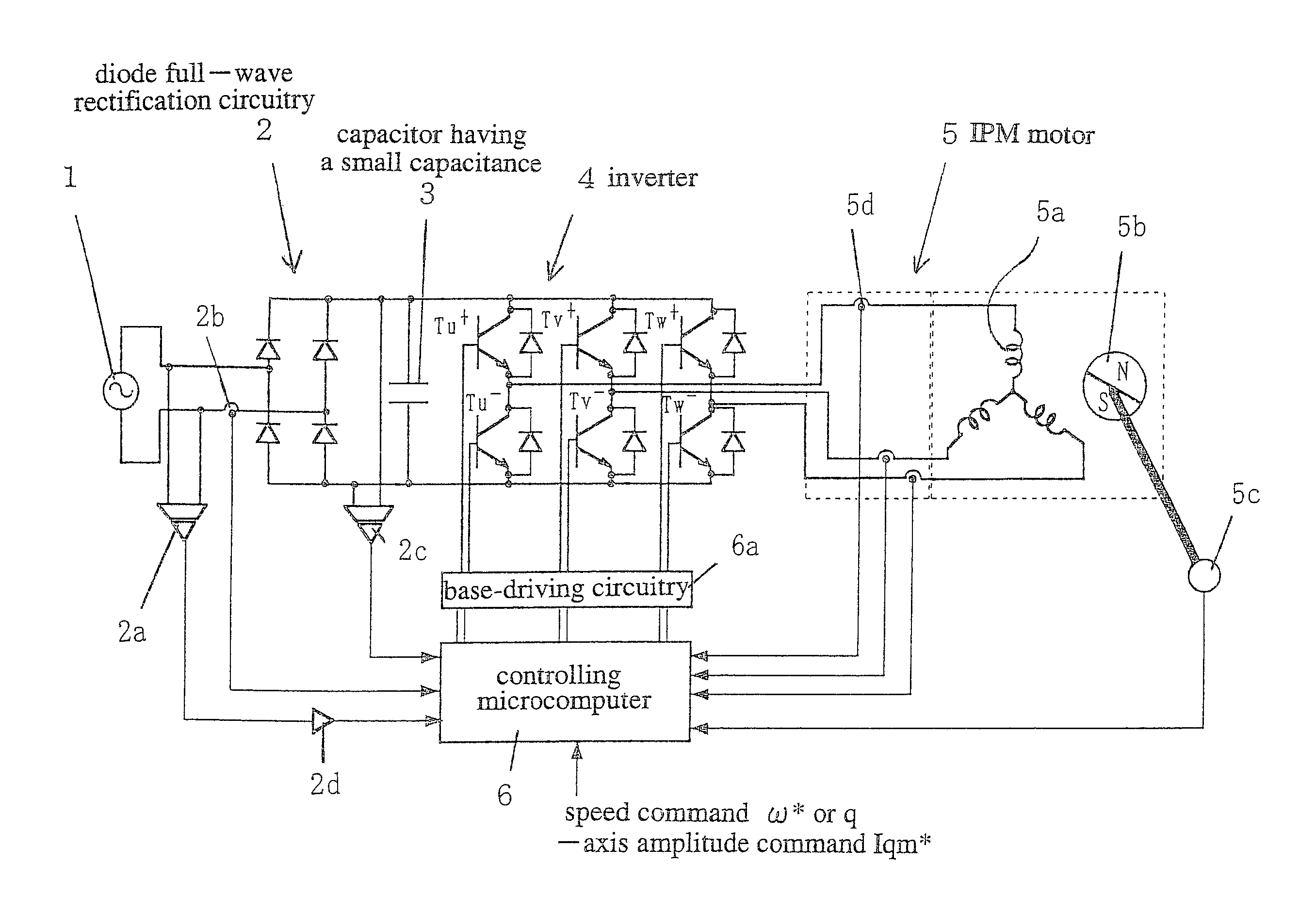
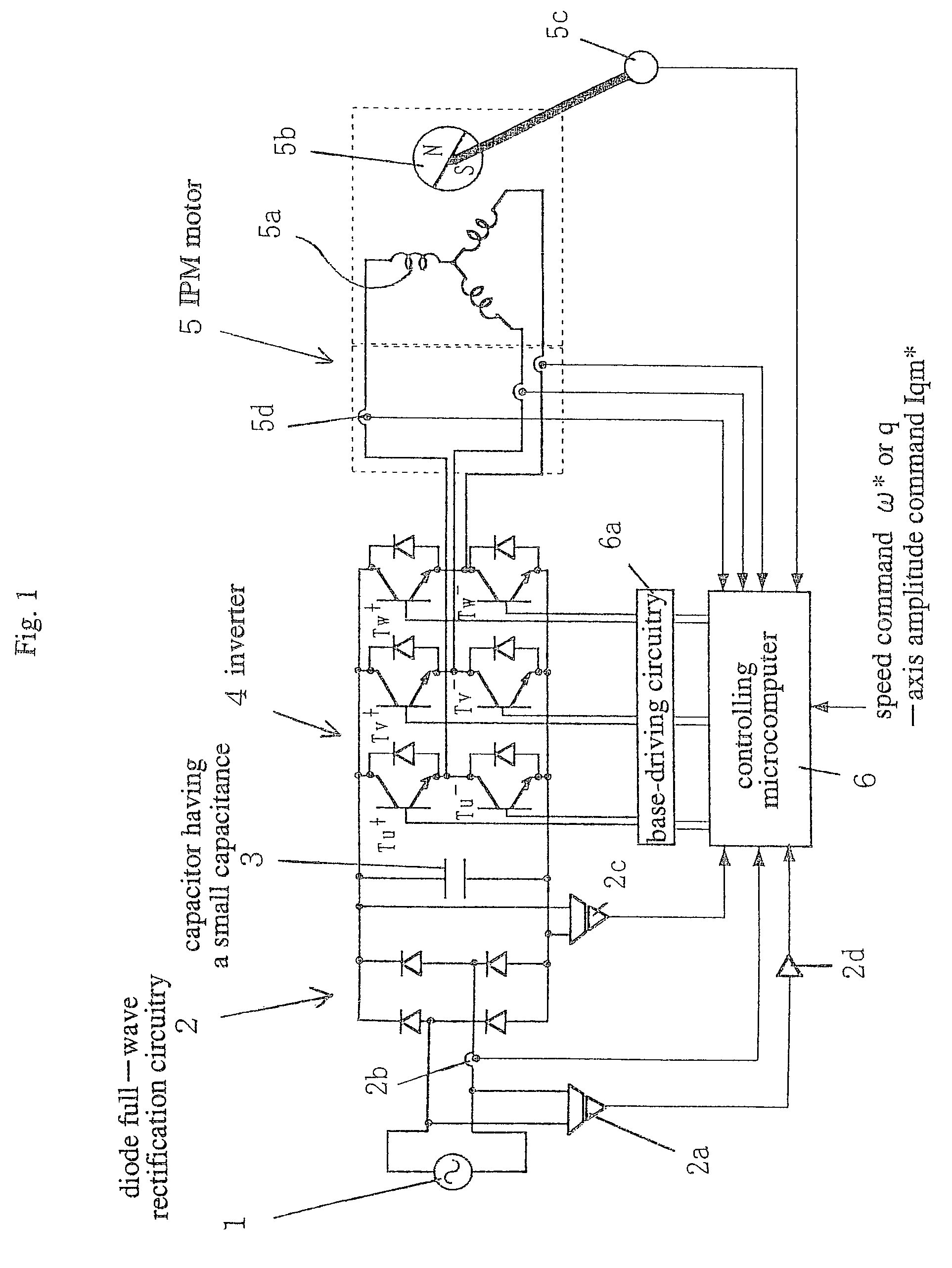
[0097]FIG. 1 is a diagram schematically illustrating a controlling system which includes an inverter controlling apparatus according to the present invention therein.

[0098]This controlling system comprises a diode full-wave rectification circuitry (single-phase rectification circuitry) 2 which receives an AC power source 1 as an input, a capacitor 3 having a small capacitance (for example, a film condenser) which is connected between output terminals of the diode full-wave rectification circuitry 2, an inverter (three-phase inverter) 4 which receives an output voltage from the diode full-wave rectification circuitry 2 as an input, an IPM motor 5 having a rotor 5b and stator windings 5a which are supplied outputs from the inverter 4, a position detection section 5c for detecting a rotational position (magnetic pole...


PUM


Abstract

An inverter controlling method is applied in a system comprising a single-phase rectification circuitry and three-phase inverter. The method determines a capacitance of a capacitor connected between output terminals of the single-phase rectification circuitry for allowing an output voltage of the single-phase rectification circuitry to pulsate at twice frequency with respect to a power frequency; controls the three-phase inverter for supplying output voltages or output currents from the three-phase inverter to a motor; and suppresses a current flowing into the capacitor from a power source via the single-phase rectification circuitry.

Description

[0001]This application is the national phase under 35 U.S.C. § 371 of PCT International Application No. PCT / JP02 / 04969 which has an International filing date of May 22, 2002, which designated the United States of America.TECHNICAL FIELD[0002]The present invention relates to an inverter controlling method and apparatus thereof. More particularly, the present invention relates to a method and apparatus for controlling a three-phase inverter, for supplying output voltages or output currents of the three-phase inverter to a motor, which method and apparatus include therein a single phase rectification circuitry and the three-phase inverter and determine a capacitance of a capacitor connected between output terminals of the single phase rectification circuitry so as to pulsate an output voltage of the single phase rectification circuitry by a frequency which is twice of a power frequency.BACKGROUND ART[0003]As is known from the past, an inverter circuitry is a circuitry which transforms ...

Claims


Application Information

Patent Timeline
IPC IPC(8): H02P7/28H02M5/458H02M7/48
CPCH02M1/425H02M5/458H02P23/0081H02M7/53873Y02B70/126H02M2001/0012H02P23/26H02M1/0012Y02B70/10H02M7/48H02P27/05
Inventor TAKAHASHI, LEGAL REPRESENTATIVE, YUKOJIBIKI, LEGAL REPRESENTATIVE, MIWATAKAHASHI, LEGAL REPRESENTATIVE, MINAKOTAKAHASHI, LEGAL REPRESENTATIVE, MAMORUYAMAI, HIROYUKITAKAHASHI, DECEASED, ISAO
Owner DAIKIN IND LTD
Why Eureka
Try Eureka