System and method for rapid heating of fluid

a fluid heating and fluid technology, applied in the field of apparatus, can solve the problems of increasing the cost of electric hot water storage,

Inactive Publication Date: 2006-05-23
MICROHEAT TECH PTY LTD
View PDF6 Cites 43 Cited by
  • Summary
  • Abstract
  • Description
  • Claims
  • Application Information

AI Technical Summary

Benefits of technology

[0041]Such a step may be performed by controlling the electrical power applied to the electrode sets to maintain the required constant fluid temperature increase in that electrode segment. The variable electrical voltage may then be adjusted to compensate for changes in specific conductance of the fluid within the segment of the flow path associated with each electrode pair, which will affect the current drawn by the fluid in that segment. The changes in specific conductance of the fluid passing through the separate electrode segments can be managed separately in this manner. Therefore the system is able to effectively control and manage the resulting specific conductance gradient across the whole system.
[0044]The volume of fluid passing between any set of electrodes may be accurately determined by measuring the dimensions of the passage within which the fluid is exposed to the electrodes taken in conjunction with fluid flow.
[0054]Of course, the temperature of the inlet water to the electrode segments may be repeatedly measured over time and as the value for the measured inlet water temperature changes, the calculated value for the required temperature change from inlet to outlet of the electrode segments can be adjusted accordingly. Similarly, with changing temperature, mineral content and the like, changes in electrical conductivity and therefore specific conductance of the fluid may occur over time. Accordingly, the current passing through the fluid will change causing the resulting power applied to the water to change. Repeatedly measuring the temperature outputs of the electrode segments over time and comparing these with the required output temperature values will enable repeated calculations to correct the voltage applied to the electrode segments.
[0060]Relationship (2) below, facilitates the calculation of the electrical power to be applied as accurately as possible, almost instantaneously. This eliminates the need for unnecessary water usage otherwise required to initially pass through the system before facilitating the delivery of water at the required temperature. This provides the potential for saving water.
[0063]As part of the initial heating sequence, the applied voltage may be set to a relatively low value in order to determine the initial specific conductance of the fluid passing between the electrodes. The application of voltage to the electrodes will cause current to be drawn through the fluid passing therebetween thus enabling determination of the specific conductance of the fluid, as it is directly proportional to the current drawn therethrough. Accordingly, having determined the electrical power that should be supplied to the fluid flowing between the electrodes in the electrode segments, it is possible to determine the required voltage that should be applied to those electrodes in order to increase the temperature of the fluid flowing between the electrodes in the electrode segments by the required amount. The instantaneous current being drawn by the fluid is preferably continually monitored for change along the length of the heating path. Any change in instantaneous current drawn at any position along the heating path is indicative of the change in electrical conductivity or specific conductance of the fluid. The varying values of specific conductance apparent in the fluid passing between the electrodes in the electrode segments, effectively defines the specific conductivity gradient along the heating path.

Problems solved by technology

Of course, as it is generally known, the generation of electricity by the burning of fossil fuels significantly contributes to pollution and global warming.
Electric hot water storage systems are generally considered to be energy inefficient as they operate on the principle of storing and heating water to a predetermined temperature greater than the temperature required for usage, even though the consumer may not require hot water until some future time.
As thermal energy is lost from the hot water in the storage tank, further consumption of electrical energy may be required to reheat that water to the predetermined temperature.
However, during that time, some electric hot water storage systems continue to consume energy to heat the water in preparation for a consumer requiring hot water at any time.
However, whilst it is possible to use natural gas fuel sources for the rapid heating of water, these sources are not always readily available.
There have been previous ineffective attempts to produce an electrical “instant” hot water system.
Whilst this type of system avoids the energy inefficiencies involved with the storage of hot water, it unfortunately suffers a number of other disadvantages.
This has the disadvantageous effect of causing the formation of crystals of dissolved salts normally present in varying concentrations in water such as calcium carbonate and calcium sulphate.
Hot areas of the wire in direct contact with the water provide an excellent environment for the formation of these types of crystals which results in the wire becoming “caked” and thus reducing the efficiency of thermal transfer from the wire to the surrounding water.
In addition, hot wire type systems require relatively high water pressures for effective operation and thus these systems are not effective for use in regions that have relatively low water pressure or frequent drops in water pressure that may occur during times of peak water usage.
In this case currents induced into a secondary winding of the transformer cause the secondary winding to heat up.
Whilst this type of system avoids the energy inefficiencies involved with the storage of hot water, it also suffers a number of other disadvantages.
In addition, the magnetic fields developed and the high currents induced in the secondary winding may result in unacceptable levels of electrical or RF noise.
This electrical or RF noise can be difficult to suppress or shield, and affects other electromagnetic susceptible devices within range of the electromagnetic fields.

Method used


Image

  • System and method for rapid heating of fluid
  • System and method for rapid heating of fluid
  • System and method for rapid heating of fluid

Examples


Embodiment Construction

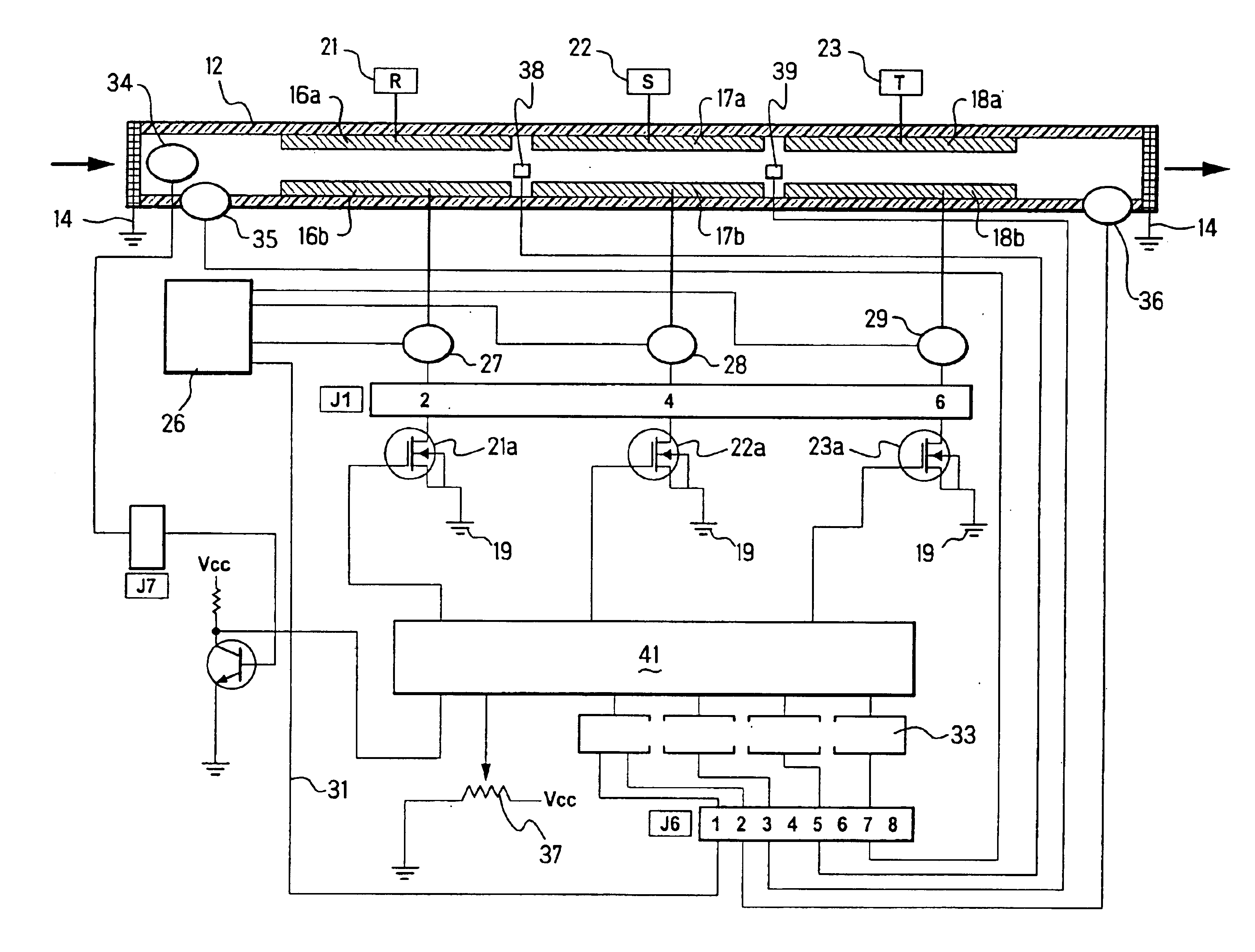
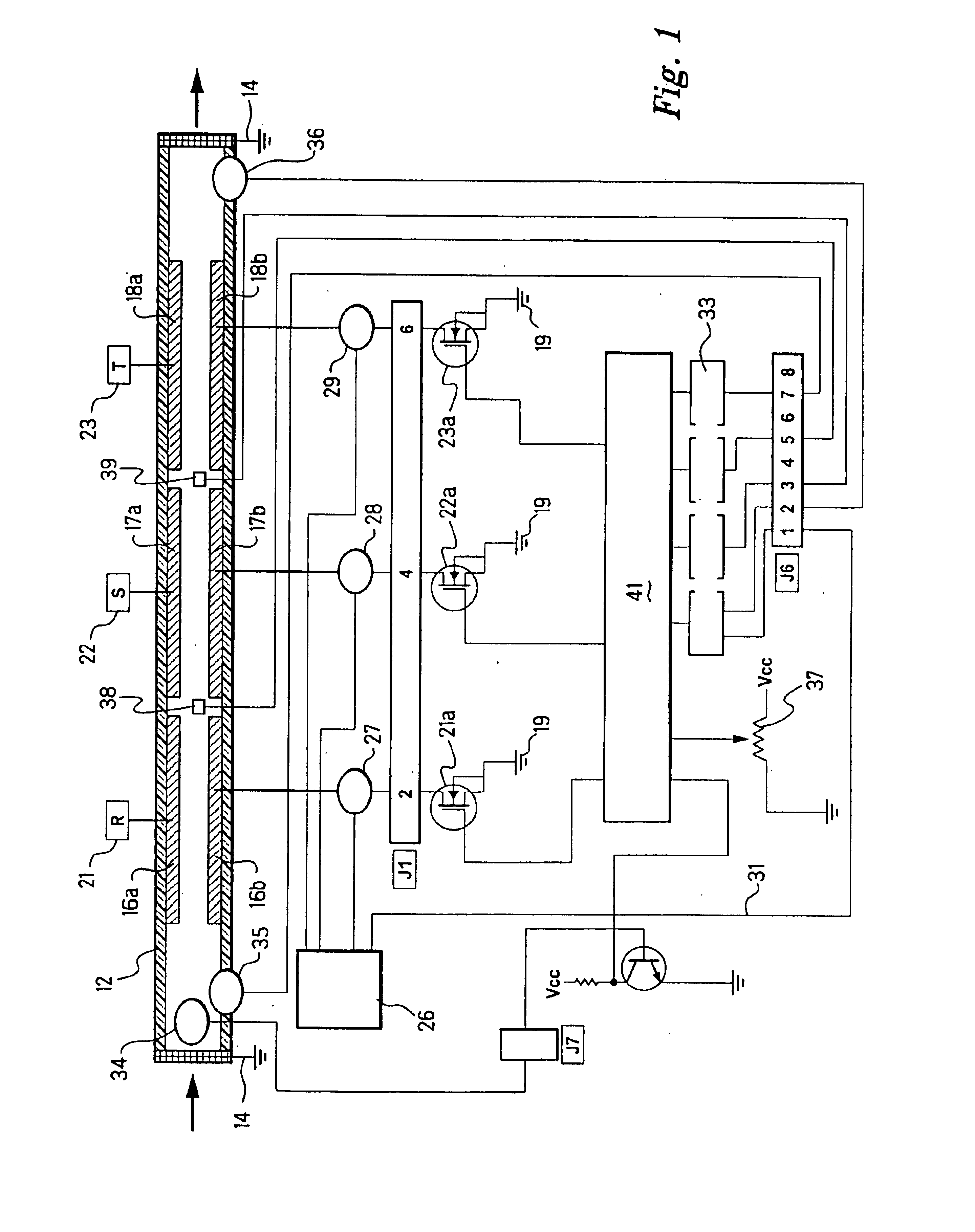
[0069]Referring to the drawings, FIG. 1 shows a schematic block diagram of a heating system of one embodiment in which water is caused to flow through a pipe or tube 12. The tube 12 is preferably made from a material that is electrically non-conductive, such as synthetic plastic material. However, the tube 12 is likely to be connected to metallic water pipe, such as copper tubing, that is electrically conductive. Accordingly, earth straps 14 are included at each end of the tube 12 for electrically earthing any metal tubing connected to the tube 12. The earth straps 14 would ideally be connected to an electrical earth of the electrical installation in which the heating system of the embodiment was installed. As the earth straps may draw current from an electrode through water passing through the tube 12, activation of an earth leakage circuit breaker or residual current device (RCD) may be effected. In a particularly preferred form of this embodiment, the system includes earth leakag...


PUM


Abstract

Apparatus for rapidly heating fluid includes a fluid circuit having electrodes between which the fluids flows. A voltage is applied between a pair of electrodes whereby current is caused to flow through the fluid. The inlet and outlet fluid temperatures are measured and the current controlled by varying the applied voltage to produce a desired temperature rise in the fluid in accordance with measured fluid flow rate.

Description

FIELD OF THE INVENTION[0001]The present invention relates to an apparatus, a system and method for the rapid heating of fluid and more particularly, to an apparatus, system and method for rapidly heating fluid using electrical energy.BACKGROUND OF THE INVENTION[0002]Hot water systems of one form or another are installed in the vast majority of residential and business premises in developed countries. In some countries, the most common energy source for the heating of water is electricity.[0003]Of course, as it is generally known, the generation of electricity by the burning of fossil fuels significantly contributes to pollution and global warming. For example, in 1996, the largest electricity consuming sector in the United States were residential households, which were responsible for 20% of all carbon emissions produced. Of the total carbon emissions from this electricity-consuming sector, 63% were directly attributable to the burning of fossil fuels used to generate electricity fo...

Claims


Application Information

Patent Timeline
Patent Type & Authority Patents(United States)
IPC IPC(8): H05B3/60H05B3/00F24H1/10F24H9/20
CPCF24H1/106F24H9/2028G05D23/1931H05B3/44H05B3/146H05B2203/021H05B2203/005F24H15/281F24H15/238F24H15/219F24H15/212F24H15/414F24H15/215F24H15/144F24H15/37F24H15/174
Inventor ISRAELSOHN, CEDRICVAN AKEN, ROBERT C.
Owner MICROHEAT TECH PTY LTD
Why Eureka
Try Eureka