
Manufacturing method and bonding apparatus with vacuum chuck with independent retaining portions for liquid crystal (LCD) device

a technology of liquid crystal display and manufacturing method, which is applied in non-linear optics, instruments, optics, etc., can solve the problems of difficult to achieve higher positioning accuracy, substrate cannot be securely held, and the cell assembly timeline is considered shorter, so as to achieve accurate bonding between the substrate and the bonded area.

Active Publication Date: 2006-05-23
TWITTER INC
View PDF9 Cites 43 Cited by
  • Summary
  • Abstract
  • Description
  • Claims
  • Application Information

AI Technical Summary

Benefits of technology

[0022]Another object of the present invention is to provide a manufacturing method and a bonding apparatus for a liquid crystal display device that allow two substrates to be accurately bonded to each other without dislocation.
[0025]In this case, the two substrates are further firmly positioned, making it possible to accurately bond the two substrates without dislocation. Preferably, the bonding step is carried out in an atmosphere of 100 to 100 kPa, or more preferably 2.7 k to 50 kPa. In this case, the bonding is performed in an area of low vacuum closer to atmospheric pressure, as compared with the degree of vacuum (1 to 10 Pa) in a conventional bonding step, so that the time required for evacuating is reduced, resulting in a higher throughput. Moreover, a vacuum system of the apparatus can be simplified, permitting reduced cost of the apparatus. In addition, as described above, only a part of each of the substrates is brought into contact first, and then the contact region is gradually expanded. This arrangement makes it possible to adequately eliminate remaining bubbles even at low vacuum.
[0029]Additionally, in a preferred embodiment, the second vacuum chuck further includes a holder for pressing the second substrate. The predetermined region is pressed by the holder in the bonding step. In this case, the holder retains the two substrates further firmly, making it possible to accurately bond the two substrates without dislocation.
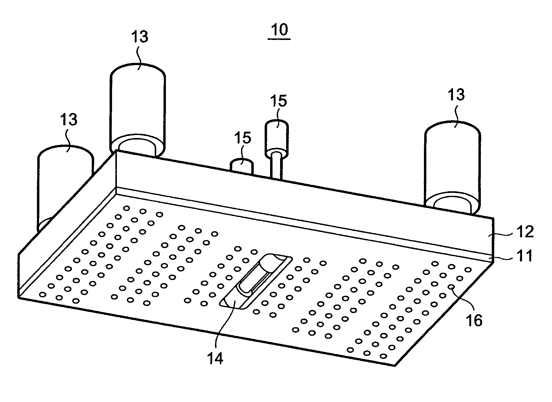
[0031]In this bonding apparatus, the retaining region at the center stops its retaining operation first, causing the region attracted to that particular retaining region of the second substrate to come off the second vacuum chuck and to be bonded to the first substrate. Subsequently, an outer retaining region adjacent to that particular retaining region also stops its retaining operation, causing the region that has been attracted to the retaining region to be also bonded to the first substrate. Repeating this operation gradually increase the bonded area. As a result, the two substrates can be bonded to each other while expelling bubbles out from the liquid crystal. Preferably, the second vacuum chuck further includes a holder for pressing the second substrate. In this case, the holder retains the two substrates further firmly, making it possible to accurately bond the two substrates without dislocation.

Problems solved by technology

In other words, the ODF method leads to a significantly reduced time for the liquid crystal injection step, which results in a considerably shorter cell assembly timeline, whereas the conventional cell assembly process requires a lengthier period for injecting a liquid crystal.
This makes it difficult to achieve higher accuracy of positioning.
The vacuum holding method, however, is disadvantageous in that a substrate cannot be securely held because a pressure difference cannot be obtained between the pressure of the atmosphere and the pressure at which the chuck attracts the substrate when the bonding step is carried out in an intermediate vacuum atmosphere in order to prevent bubbles from remaining in a liquid crystal.
The electrostatic holding method, however, may cause electrostatic damage to a substrate because a voltage of a few thousand volts is applied to retain a substrate.
Furthermore, loading and unloading a chuck takes time, so that the bonding step takes time.
There is another disadvantage in that the chuck used in the electrostatic holding method is extremely expensive.
Japanese Patent documents 2 and 3 disclose methods wherein remaining bubbles are prevented by changing the air pressure of the atmosphere in which the bonding step is carried out; this, however, requires a time to change the air pressure, undesirably leading to a longer bonding time.Patent document 1: Japanese Unexamined Patent Application Publication No. 11-231328Patent document 2: Japanese Unexamined Patent Application Publication No. 2000-258777Patent document 3: Japanese Unexamined Patent Application Publication No. 2001-330840Patent document 4: Japanese Unexamined Patent Application Publication No. 2002-284295Patent document 5: Japanese Unexamined Patent Application Publication No. 2002-137352
Unfortunately, despite these efforts, a suitable manufacturing method and a bonding apparatus for a liquid crystal display device that allow two substrates to be bonded to each other while expelling bubbles out from a liquid crystal remains desired.

Method used


Image

  • Manufacturing method and bonding apparatus with vacuum chuck with independent retaining portions for liquid crystal (LCD) device
  • Manufacturing method and bonding apparatus with vacuum chuck with independent retaining portions for liquid crystal (LCD) device
  • Manufacturing method and bonding apparatus with vacuum chuck with independent retaining portions for liquid crystal (LCD) device

Examples


Embodiment Construction

[0044]The use of figure reference labels in the claims is intended to identify one or more possible embodiments of the claimed subject matter in order to facilitate the interpretation of the claims. Such labeling is not to be construed as necessarily limiting the scope of those claims to the embodiments shown in the corresponding figures. The preferred embodiments of the present invention and its advantages are best understood by referring to the drawings, like numerals being used for like and corresponding parts of the various drawings. Reference herein to “one embodiment” or “an embodiment” means that a particular feature, structure, or characteristic described in connection with the embodiment can be included in at least one embodiment of the invention, but not necessarily in all. The appearances of the phrase “in one embodiment” in various places in the specification, sequentially or otherwise, does not necessarily indicate that each phrase refers to or is used in reference to t...


PUM

PropertyMeasurementUnit
voltageaaaaaaaaaa
atmospheric pressureaaaaaaaaaa

Abstract

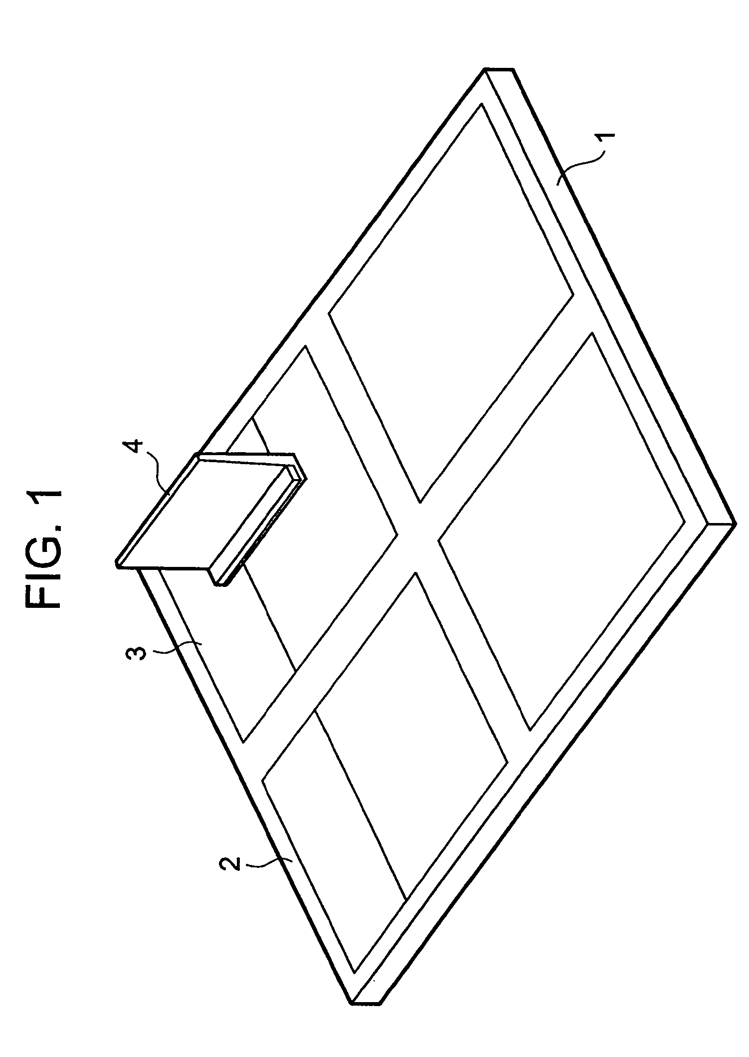
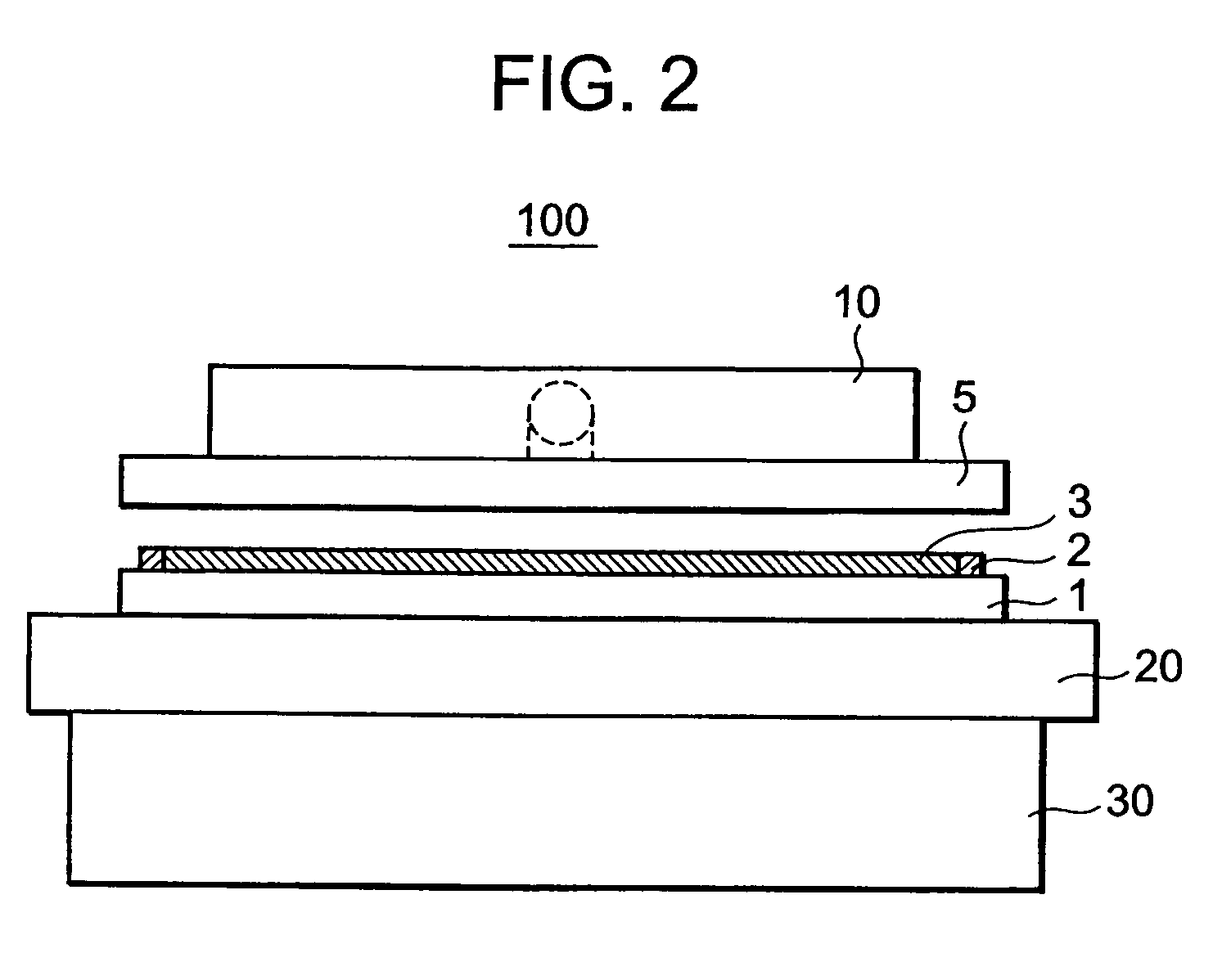
A manufacturing method and a bonding apparatus for a liquid crystal display device is provided for that makes it possible to expel remaining bubbles from a liquid crystal and to bond an array substrate and a color filter substrate while maintaining their positional relationship. In a step for bonding an array substrate with a liquid crystal applied thereto and a color filter substrate, vacuum holding of only a central retaining region of an upper vacuum chuck of the bonding apparatus is stopped. This causes the central portion of the color filter substrate to come in contact with the array substrate due to its own weight. The contact region is pressed by a holder to secure the positional relationship between the array substrate and the color filter substrate. Thereafter, with the elapse of time, the upper vacuum chuck increases the retaining region for which a vacuum retaining operation is stopped so as to expand the area of contact between the array substrate and the color filter substrate. As a result, bubbles in the liquid crystal are expelled externally.

Description

BACKGROUND OF THE INVENTION[0001]1. Field of the Invention[0002]The present invention relates to a manufacturing method and a bonding apparatus for a liquid crystal display (LCD) device and, more particularly, to a manufacturing method and a bonding apparatus for a liquid crystal display device in a cell assembly step and a liquid crystal injection step.[0003]2. Description of Related Art[0004]In a cell assembly step, in a manufacturing process of a liquid crystal display device (hereinafter referred to also as “LCD”), a manufacturing method known as one drop fill (hereinafter referred to as “ODF”) has recently been receiving attention. According to the ODF method, a sealant and a liquid crystal are applied to an array substrate before bonding the array substrate with a color filter substrate. This allows the ODF method to reduce the time required for injecting a liquid crystal in a conventional cell assembly process. In other words, the ODF method leads to a significantly reduced t...

Claims


Application Information

Patent Timeline
Patent Type & Authority Patents(United States)
IPC IPC(8): G02F1/13G02F1/1339G02F1/1341
CPCG02F1/1341
Inventor YOKOUE, TOSHIYUKI
Owner TWITTER INC
Learn More