Fuel cell

a fuel cell and cell technology, applied in the field of fuel cells, can solve the problems of low rigidity of separators, difficult to produce a large electricity, and the electrical membrane of stabilized zirconia cannot be very thin for maintaining sufficient mechanical strength, and achieve the effect of simple structur

Inactive Publication Date: 2006-05-23
HONDA MOTOR CO LTD
View PDF10 Cites 9 Cited by
  • Summary
  • Abstract
  • Description
  • Claims
  • Application Information

AI Technical Summary

Benefits of technology

[0013]A main object of the present invention is to provide a fuel cell including a plurality of electrolyte electrode assemblies with a compact and simple structure, in which an oxygen-containing gas is reliably supplied to the fuel cell, and the pressure is uniformly applied to electrode surfaces.
[0016]A first ridge is formed on the first plate, and a second ridge is formed on the second plate. The first ridge and the second ridge protrude away from each other to form the oxygen-containing gas channel between the first ridge and the second ridge. The first plate includes a first outer projection and a first inner projection on opposite sides of the first ridge. The second plate includes a second outer projection and a second inner projection on opposite sides of the second ridge. The first outer projection and the first inner projection protrude oppositely to the first ridge, and the second inner projection and the second outer projection protrude oppositely to the second ridge such that the first outer projection and the second outer projection are in contact with each other, and the first inner projection and the second inner projection are in contact with each other. The first outer projection and the second outer projection are in contact with each other, and the first inner projection and the second inner projection are in contact with each other around a space of the oxygen-containing gas channel. Therefore, the rigidity of the fuel cell around the space of the oxygen-containing gas channel is good. When the separators are tightened in the stacking direction of the fuel cells, the pressure is uniformly applied to the surfaces of the electrodes, and the space of the oxygen-containing gas channel is not deformed. It is possible to supply the oxygen-containing gas to each of the electrolyte electrode assemblies uniformly, and achieve the desired power generation performance of the fuel cell. Further, the sealing characteristics between the first plate and the second plate are improved effectively.
[0017]The first ridge is formed integrally with the first plate, and extends around a curved outer section of the first plate. The second ridge is formed integrally with the second plate, and extends around a curved outer section of the second plate. The first outer projection and the first inner projection are formed integrally with the first plate. The second outer projection and the second inner projection are formed integrally with the second plate. Thus, the rigidity of the first plate and the second plate is improved desirably, and the number of steps for forming the first plate and the second plate can be reduced.
[0019]The oxygen-containing gas channel and the exhaust gas channel are formed only by the first separator and the second separator. Thus, the production of the fuel cell is simply performed. Since dedicated pipes or the like are not needed for the oxygen-containing gas channel and the exhaust gas channel, the number of components of the fuel cell is small. Further, since a space is formed between the first ridge of the first separator and the second ridge of the second separator, the heights of the first ridge and the second ridge can be small. When the first plate and the second plate are formed under pressure, the amount of drawing for each of the first ridge, the second ridge, the first and second outer projections, and the first and second inner projections is small. Therefore, the first plate and the second plate can be formed with a high degree of accuracy.
[0020]Further, a seal for sealing the oxygen-containing gas channel is formed between the first ridge formed on the first plate of one of the separators and the second ridge formed on the second plate of the other of the separators. Thus, the pressure is uniformly applied to the seal. With the simple structure, the sealing is performed reliably.
[0021]The electrolyte electrode assemblies are arranged along at least one circle around a center of the separators. Therefore, the oxygen-containing gas is supplied to the each of the electrolyte electrode assemblies, and the power generation is performed uniformly, and the size of the fuel cell is effectively reduced.

Problems solved by technology

However, the electrolyte membrane of the stabilized zirconia can not be very thin for maintaining the sufficient mechanical strength.
Therefore, it is difficult to produce a large electricity using the membrane of stabilized zirconia in the solid oxide fuel cell.
Therefore, the rigidity of the separators is low.
Since a substantial space corresponding to the thickness of the cells is formed between outer circumferential regions of the separators, the outer circumferential regions of the separators may be deformed, and thus, gas leakage may occur.
Therefore, the desired power generation performance may not be maintained.
Therefore, when the fuel cell stack is tightened by a bolt, for example, the pressure may not be uniformly applied to the entire surface of the separators 2.
Thus, the fuel cell stack may be deformed undesirably.
If the unit cell 1 is damaged, gas leakage may occur due to the sealing failure.

Method used


Image

  • Fuel cell
  • Fuel cell
  • Fuel cell

Examples


first embodiment

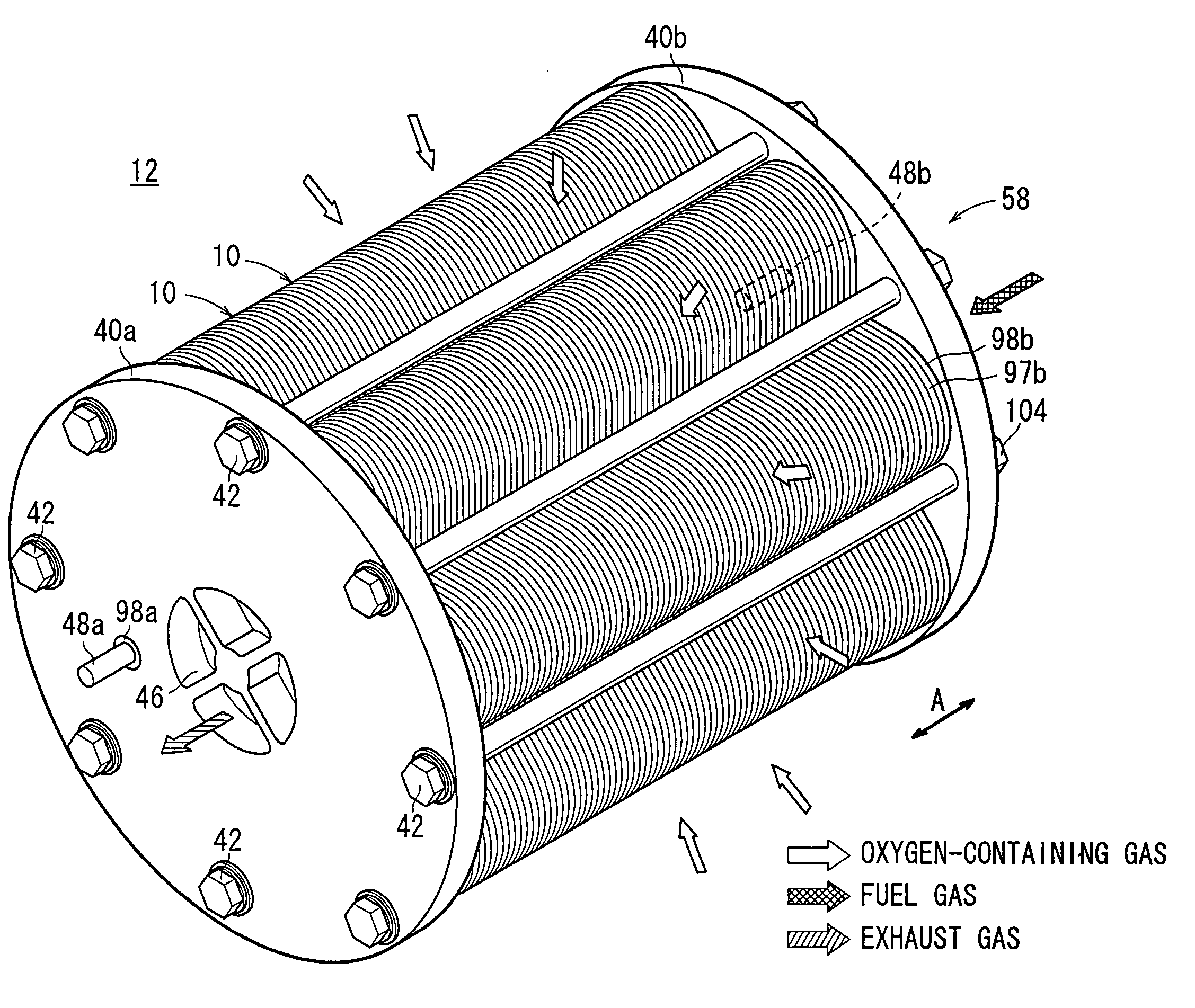
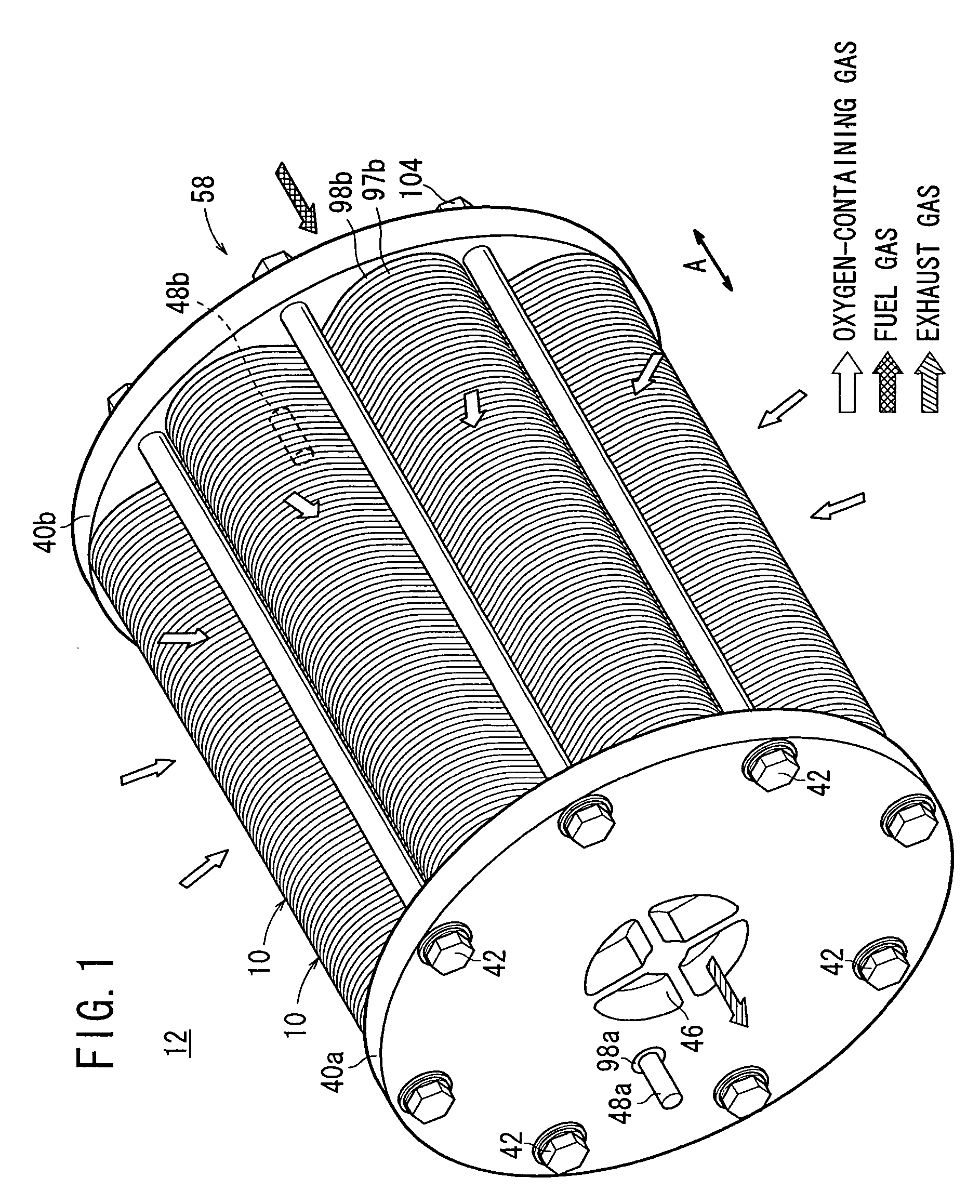
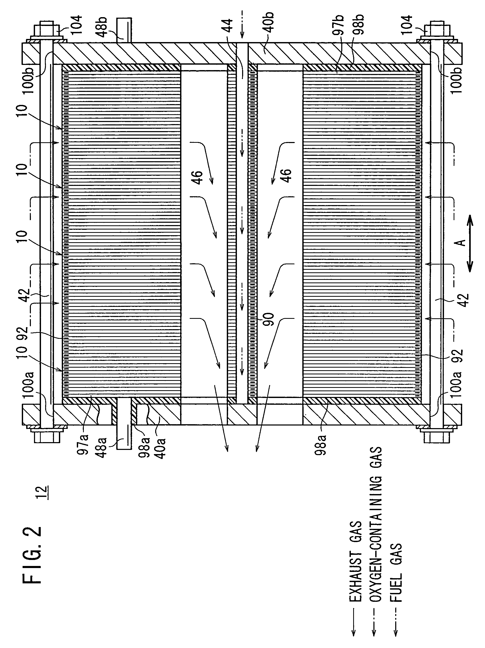
[0040]FIG. 1 is a perspective view schematically showing a fuel cell stack 12 formed by stacking a plurality of fuel cells 10 according to the present invention, and FIG. 2 is a cross sectional view showing a part of the fuel cell stack 12.

[0041]The fuel cell 10 is a solid oxide fuel cell (SOFC) for stationary and mobile applications. For example, the fuel cell 10 is mounted on vehicles. In an example of the first embodiment shown in FIG. 3, the fuel cell stack 12 is used in a gas turbine 14. In FIG. 3, the shape of the fuel cell stack 12 is different from those shown in FIGS. 1 and 2, however, the structure is substantially the same.

[0042]The fuel cell stack 12 is disposed in a casing 16 of the gas turbine 14. A combustor 18 is disposed at the center of the fuel cell stack 12. The fuel cell stack 12 discharges an exhaust gas as a mixed gas of a fuel gas and an oxygen-containing gas after reaction into a chamber 20 toward the combustor 18. The chamber 20 is narrowed in a flow direct...

third embodiment

[0099]FIG. 15 is a cross sectional view schematically showing a gas turbine 130 including relatively large fuel cell stacks 12b according the present invention, and FIG. 16 is a front view showing the gas turbine 130.

[0100]In the gas turbine 130, four fuel cell stacks 12b are arranged along a first circle in the casing 132 at intervals of 90° and four fuel cell stacks 12b are arranged along a second circle in the casing 132 at intervals of 90°. The first circle is spaced from the second circle at a predetermined distance in an axial direction of the casing 132 indicated by an arrow X. Orientation of the four fuel cell stacks 12b arranged along the first circle is shifted by 45° from the second fuel cell stacks 12b arranged along the second circle. Therefore, the fuel cell stacks 12b do not contact with each other. Each of the fuel cell stacks 12b is covered by a cover 134, and a hot air supply passage 136 is formed inside the cover 134.

[0101]In the gas turbine 130, the four fuel cel...


PUM

PropertyMeasurementUnit
temperatureaaaaaaaaaa
ion-conductiveaaaaaaaaaa

Abstract

Each of separators for sandwiching a plurality of electrolyte electrode assemblies includes a pair of plates. A fuel gas channel and an oxygen-containing gas channel are formed between the plates. First and second circumferential ridges are formed integrally on curved outer sections of the plates to protrude away from each other. Further, outer projections and inner projections are formed integrally on opposite sides of the first and second circumferential ridges to protrude toward each other.

Description

BACKGROUND OF THE INVENTION[0001]1. Field of the Invention[0002]The present invention relates to a fuel cell having a plurality of electrolyte electrode assemblies interposed between separators. Each of the electrolyte electrode assemblies includes an anode, and a cathode, and an electrolyte interposed between the anode and the cathode.[0003]2. Description of the Related Art:[0004]Typically, a solid oxide fuel cell (SOFC) employs an electrolyte of ion-conductive solid oxide such as stabilized zirconia. The electrolyte is interposed between an anode and a cathode to form an electrolyte electrode assembly. The electrolyte electrode assembly is interposed between separators (bipolar plates), and the electrolyte electrode assembly and the separators make up a unit of fuel cell for generating electricity. A predetermined number of fuel cells are stacked together to form a fuel cell stack.[0005]In the fuel cell, an oxygen-containing gas or air is supplied to the cathode The oxygen in the ...

Claims


Application Information

Patent Timeline
Patent Type & Authority Patents(United States)
IPC IPC(8): H01M2/00H01M2/14H01M8/02H01M8/04H01M8/10H01M8/12H01M8/24
CPCH01M8/0247H01M8/0258H01M8/2425H01M8/249H01M8/0271Y02E60/50H01M8/248H01M8/04014H01M8/2483H01M8/2432H01M8/2457H01M8/2484H01M8/02
Inventor TSUNODA, TADASHI
Owner HONDA MOTOR CO LTD
Why Eureka
Try Eureka