
Runner cooling block for die casting systems

a technology of die casting system and cooling block, which is applied in the direction of molten metal supply equipment, manufacturing tools, melt-holding vessels, etc., can solve the problem that conventional runner cooling blocks only provide limited thermal dissipation levels

Inactive Publication Date: 2006-05-16
MTI ACQUISITION INC
View PDF0 Cites 6 Cited by
  • Summary
  • Abstract
  • Description
  • Claims
  • Application Information

AI Technical Summary

Problems solved by technology

However, conventional runner cooling blocks only provide limited levels of thermal dissipation.

Method used


Image

  • Runner cooling block for die casting systems
  • Runner cooling block for die casting systems
  • Runner cooling block for die casting systems

Examples


Embodiment Construction

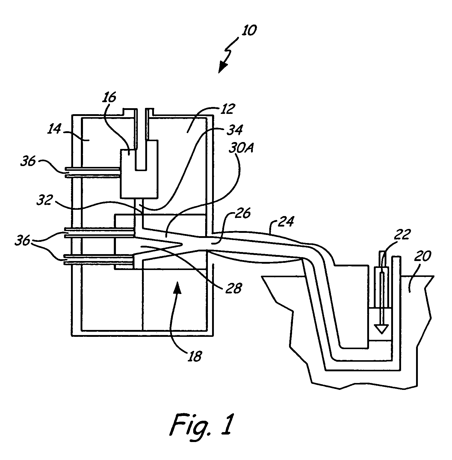
[0014]FIG. 1 shows a sectional view of die casting system 10 in which the present invention is used. The invention is typically used in zinc or magnesium hot chamber die casting operations, and can also be used in cold chamber die casting operations. Die casting system 10 includes stationary die half 12 and moving die half 14. Stationary die half 12 and moving die half 14 together comprise mold cavity 16, which has the shape of an object that can be molded with die casting system 10. Die casting system 10 also includes runner cooling block 18, which is used to control the flow of molten metal into die cavity 16. Molten metal from crucible 20 is injected with piston 22 into die casting system 10 through nozzle 24 and sprue 26 of runner cooling block 18. As molten metal enters runner cooling block 18 through sprue 26, sprue post 28 directs the flow of the molten metal into runner 30A. Runner 30A directs flow of molten metal to outlet 32, into die runner 34 and into mold cavity 16. Run...


PUM

PropertyMeasurementUnit
heat transfer rateaaaaaaaaaa
surface areaaaaaaaaaaa
circumferential heat transferaaaaaaaaaa

Abstract

A runner cooling block for use in a die casting system comprises a spreader block, a spreader, a bushing block, a sprue bushing and a water jacket. The sprue bushing comprises a sprue channel running through an interior of the sprue bushing and a cooling channel running circumferentially around an exterior surface of the sprue. The sprue bushing, water jacket and bushing block are assembled to allow cooling water to pass through the cooling channel. The spreader block and the bushing block are assembled such that the spreader is centrally located within the sprue channel wherein molten metal is allowed to pass through the sprue channel for passage into the runner system. The cooling channel includes at least one circumferential heat transfer contour to provide increased heat dissipation to enhance cooling of the molten metal passing through the sprue channel.

Description

CROSS-REFERENCE TO RELATED APPLICATION(S)[0001]The present application claims the benefit of provisional Application No. 60 / 578,634, filed Jun. 10, 2004 by Richard L. Dubay, entitled “Cooling Blocks for Molding and Casting Systems” according to 35 U.S.C. § 119(e), which is incorporated by reference in its entirety.BACKGROUND OF THE INVENTION[0002]Die casting is a popular method of forming articles of manufacture from zinc and magnesium alloys, especially for thin walled parts. Zinc and magnesium have relatively low melting points and are suited to both hot chamber die casting and cold chamber die casting. In hot chamber die casting, molten zinc or magnesium is pushed from a crucible, or pot, into a die casting system through a nozzle. The molten metal enters the die casting system through a sprue where it then travels through a runner system before entering the die cavity of a mold. The molten metal flows into the die cavity, where it solidifies and forms an article having a shape m...

Claims


Application Information

Patent Timeline
Patent Type & Authority Patents(United States)
IPC IPC(8): B22D27/04B22D17/04B22D17/08B22D17/22
CPCB22D17/04B22D17/2272B22D17/2218
Inventor DUBAY, RICHARD L.
Owner MTI ACQUISITION INC
Learn More