[0007]The present invention seeks to overcome the drawbacks and disadvantages of the above-identified prior art devices and provides an improved powered gait orthosis that is simpler and more compact. The present invention is provided with a
load cell to accurately continuously measure the weight of a patient supported on a lifting means. In addition, the lifting means includes a harness support which is adapted to swivel into different operative positions and can be locked in a particular orientation with respect to the remaining structure.
[0008]The present invention employs a
locking mechanism for the movable horizontal arms thereof which is much easier to operate than that disclosed in U.S. application Ser. No. 09 / 938,825. The drive mechanisms for the first and second depending arms are simpler than those disclosed in U.S. application Ser. No. 09 / 938,825, and are mounted closer to the depending arms to substantially reduce the distances through which the drive must be transmitted.
[0014]For the powered gait orthosis described above, the drive means for moving the first depending arm of each leg
actuator assembly includes a motor supported by the support arm of the associated leg
actuator assembly. The motor is interconnected by a belt with a
pulley drivingly connected to the first depending arm. The
pulley includes a plurality of outwardly projecting teeth matingly engaged with inwardly projecting teeth on the belt. The
pulley is connected to a shaft defining the first generally
horizontal axis by a key so as to transmit rotational motion to the first depending arm. The first depending arm is retained in position on the shaft by at least one lock nut. A sensor is provided for sensing a target mounted on the pulley and is adapted to sense the position of the target to thereby prevent over-travel of the first depending arm. The pulley includes a mechanical stop including at least two circumferentially spaced stop members adapted to engage a stop member mounted on the support arm. The mechanical stop is mounted on the pulley to prevent over-travel of the first depending arm. Alternatively, the mechanical stop includes a first cross member mounted on the support arm for bearing against an
edge surface on the first depending arm, thereby limiting pivoting of the first depending arm in a first direction, and a second cross member mounted on the first depending arm for bearing against an end surface of a member mounted to the first cross member and thereby limiting pivoting of the first depending arm in a second direction.
[0015]For the powered gait orthosis described above, the drive means for moving the second depending arm of each leg
actuator assembly includes a motor supported by the first depending arm of the associated leg actuator assembly. The motor is interconnected by a belt with a pulley drivingly connected to the second depending arm. The pulley includes a plurality of outwardly projecting teeth matingly engaged with inwardly projecting teeth on the belt. The pulley is connected to a shaft defining the second generally
horizontal axis by a key so as to transmit rotational motion to the second depending arm. The second depending arm is retained in position on the shaft by at least one lock nut. A sensor is provided for sensing a target mounted on the pulley and is adapted to sense the position of the target to thereby prevent over-travel of the second depending arm. The pulley includes a mechanical stop including at least two circumferentially spaced stop members adapted to engage a stop member mounted on the first depending arm. The mechanical stop is mounted on the pulley to prevent over-travel of the second depending arm.
[0018]For the powered gait orthosis described above, the second attachment means is supported by the second depending arm and is vertically adjustable relative thereto. The second depending arm includes at least one guide rod and a vertically movable portion slidably mounted on the guide rods. A
constant force counter
balance spring is connected to the vertically movable portion. The
constant force counter
balance spring is disposed on a shaft defining the second generally horizontal axis. A cross member is disposed within the first depending leg adjacent the
constant force counter
balance spring, and a guide mounted on the cross member prevents movement of the constant force counter balance spring along the second generally horizontal axis. The second attachment means includes a support member, and further includes locking means for locking the support member in adjusted position relative to the second depending arm. The second attachment means includes a second attachment
cuff swiveled about a substantially horizontal axis and supported by the support member. The second attachment
cuff is horizontally adjustable relative to the support member and includes locking means for locking the second attachment
cuff in a generally horizontal adjusted position relative to the support member. A laterally extending arm is connected to the vertically movable portion for mounting the first attachment means.
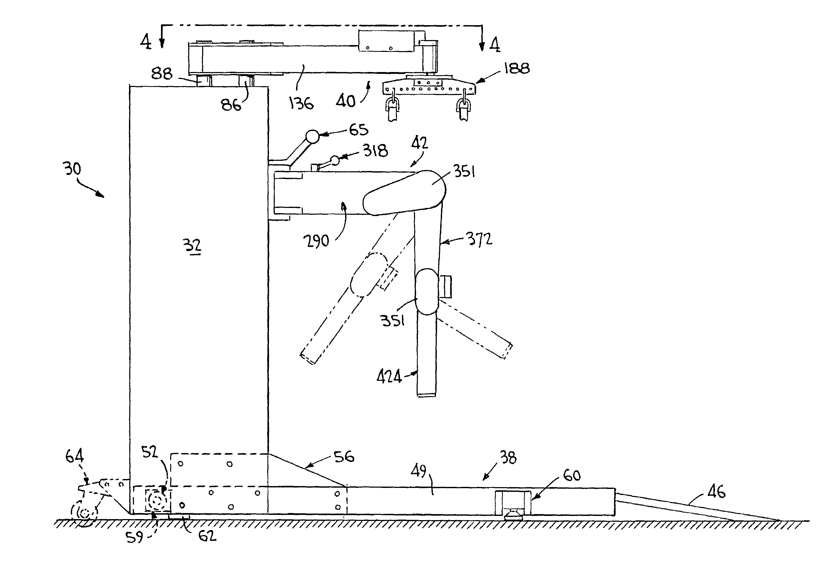
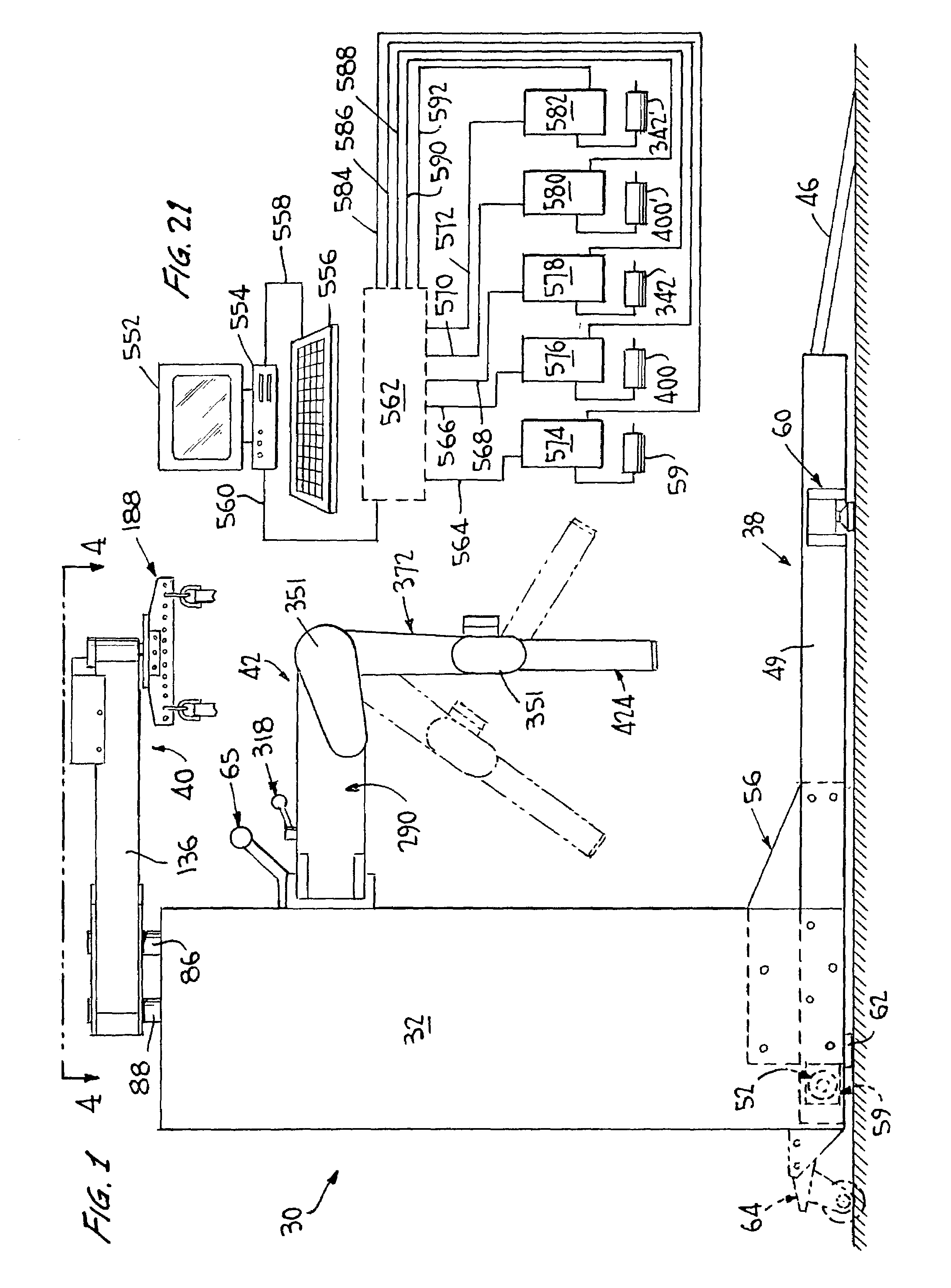
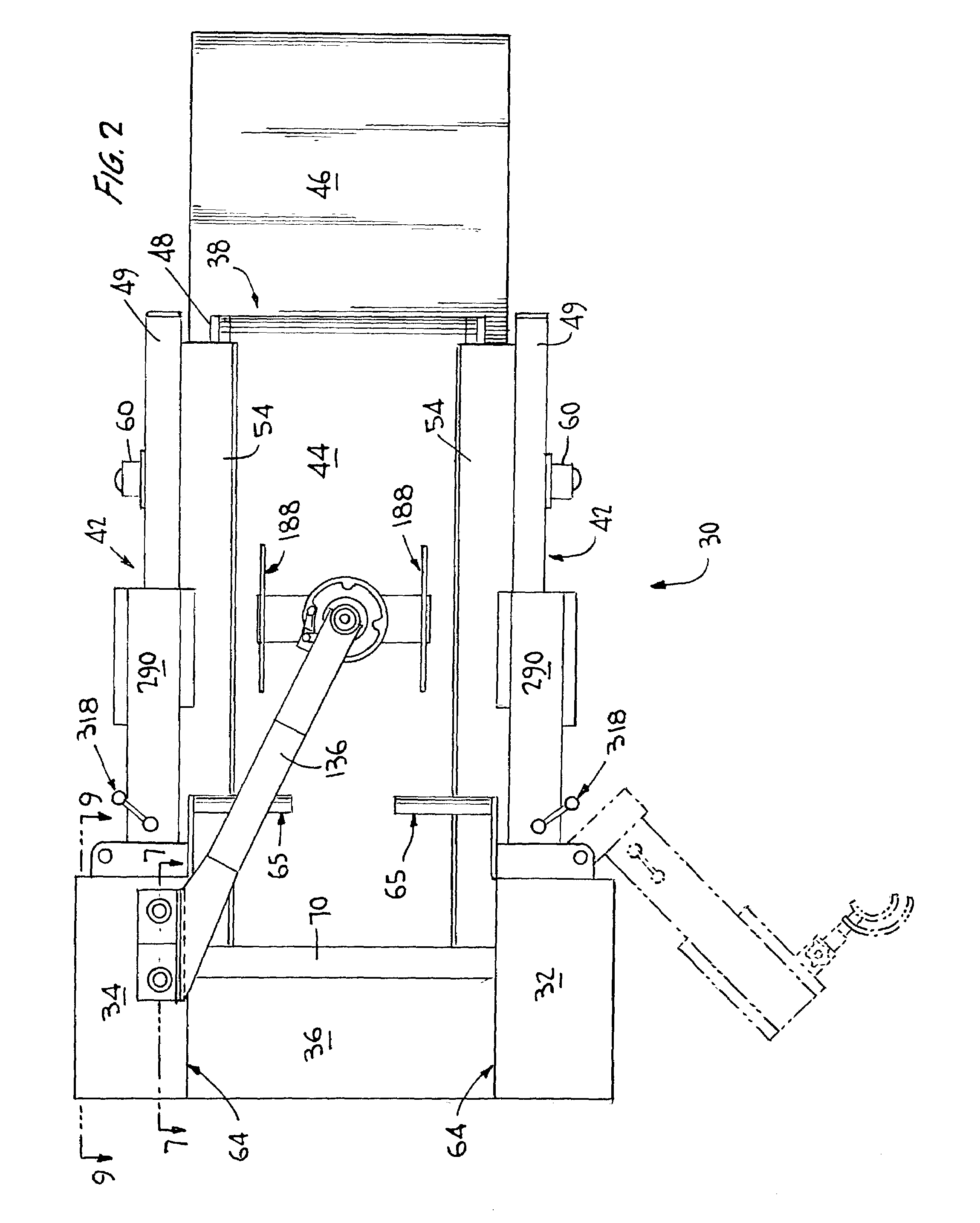
[0023]The present invention further provides a method of simulating a normal walking pattern for a patient. The method includes the steps of providing a patient with a harness and providing a powered lifting device including a harness attaching portion in a
fixed position above a powered treadmill. The method further includes the steps of moving the patient into position directly beneath the attaching portion, attaching the harness to the harness attaching portion of the lifting device, and lifting the patient and lowering the patient onto the powered treadmill. The method yet further includes the steps of providing a powered leg actuator assembly including two leg actuator portions at one side of the treadmill, attaching the first leg actuator portion to the
ankle of one leg of the patient and attaching the second leg actuator portion at a point just above the knee of the patient's leg. The method further includes the step of providing control means to separately and independently control the speed of movement of the treadmill, the first leg actuator portion and the second leg actuator portion, to coordinate the movement of the patient's leg to cause the leg to move in a desired gait. The method yet further includes the steps of varying the height of the first and second leg actuator portions relative to the treadmill in accordance with the height of a patient and providing hand holds which are grasped by the patient while the patient's leg is being moved to stabilize the patient's
torso. The method further includes the steps of sensing over-travel of the first leg actuator portion to stop the drive means for the first leg actuator portion to prevent damage to a patient's knee and sensing over-travel of the second leg actuator portion to stop the drive means for the second leg actuator portion to prevent damage to a patient's hip. The method further includes the steps of rotating the leg actuator assembly about a generally
vertical axis to a position substantially transverse and away from the treadmill so as to facilitate ingress or egress of a patient, rotating the leg actuator assembly into an operative position substantially parallel the treadmill, so as to permit attachment of the first and second leg actuator portions to the leg of the patient, and locking the leg actuator assembly into the operative position.
