
Connector module

a technology of connecting modules and cages, applied in the direction of insulated conductors, cable connections, coupling devices, etc., can solve the problems of inconvenient separation of inability to easily rework, and inability to easily separate cage top tabs and slots, etc., to achieve good emi performance

Inactive Publication Date: 2006-05-02
HON HAI PRECISION IND CO LTD
View PDF11 Cites 23 Cited by
  • Summary
  • Abstract
  • Description
  • Claims
  • Application Information

AI Technical Summary

Benefits of technology

The present invention provides a connector module that has individual component rework function, good EMI performance, and a compact structure. The connector module includes a conductive cage with pins and a shielding lid, and a cavity for receiving a signal converter. The module has a plurality of contacts that extend towards the printed circuit board and mount therein. The technical effects of the invention include improved flexibility, reliability, and durability of the connector module.

Problems solved by technology

Most of the traditional designs only provide for full connector and cage rework function.
In the prior art only can the transceiver rework, the connector and cage, which are mounted (normally soldered) on the printed circuit board, cannot easily rework.
Cooperation of the cage top tab and slot cannot be separated conveniently, particularly when there are multiple cages or other devices mounted near the cage to be worked on.
Furthermore, the cooperation of tab and slot has a clearance fit therebetween which cannot make sure of enough positive force, thus cannot achieve good electrical performance.
However, in this design removing the top cover for access to the connector for rework is further complicated because two operations are required: latches must be released and either an eye-of-needle retention must be overcome or a disordering process must be performed.
Potential for reworking the connector by treating the top as a movable hinge is not likely, as full reverse bending of the edge to clear for connector removal would result in cracks.
Additionally, because there is not enough space in cage for stiffening ribs for press-fit pins, there is no press-fit pin on the bottom wall of the shielding cage, which can reduce EMI electrical performance.
This patent does not specifically address connector rework design.
If a connector in the connector module needs to be updated or does not work, to substitute the connector with a new one is difficult and may damage a printed circuit board because the connector is normally soldered on a printed circuit board.
Furthermore, all of above-mentioned prior arts fail to provide every individual component (cage, and connector) rework function at no expense of damaging the components and deteriorating the electrical performance.

Method used


Image

  • Connector module
  • Connector module
  • Connector module

Examples


Embodiment Construction

[0020]Reference will now be made in detail to a preferred embodiment of the present invention.

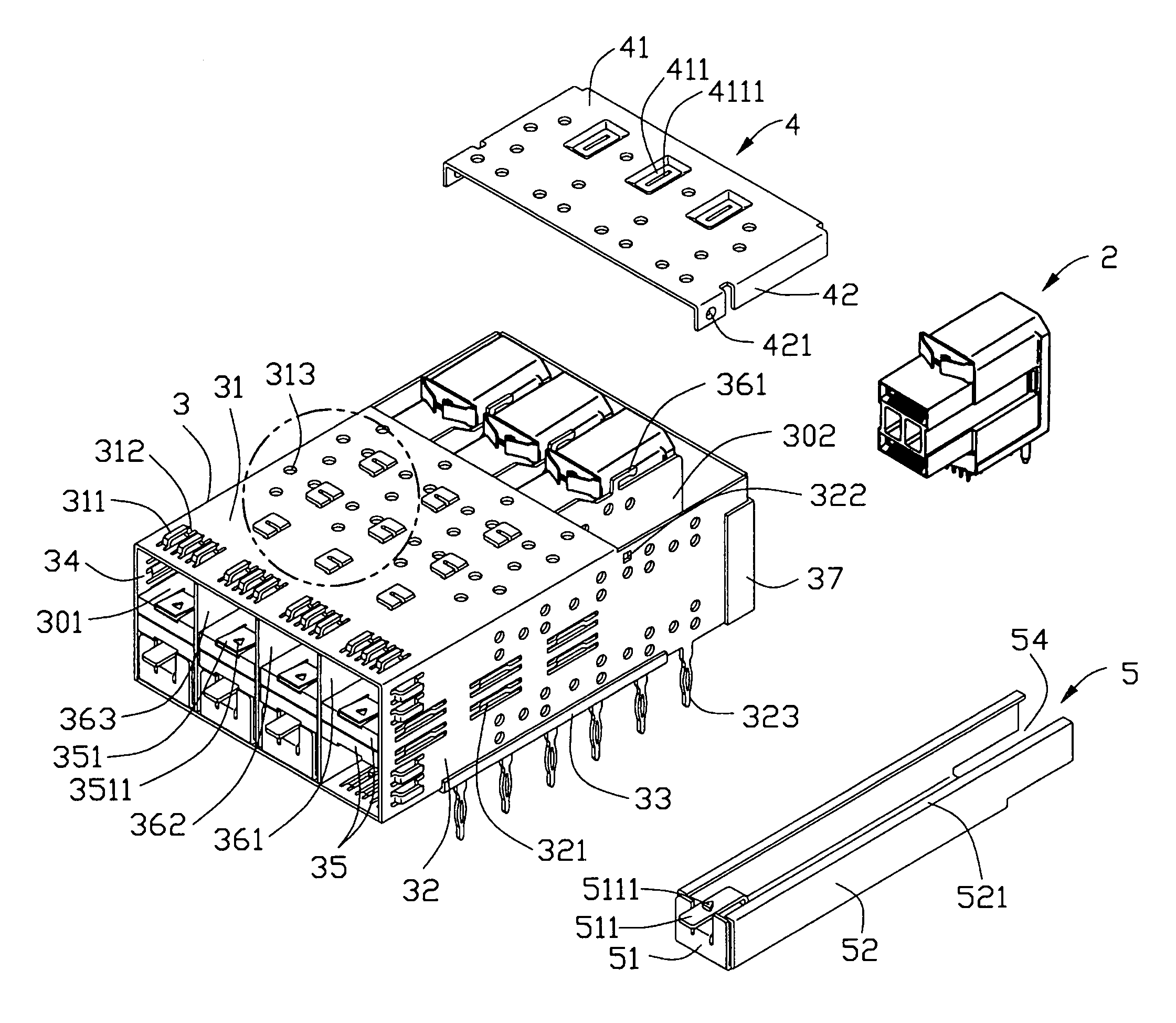
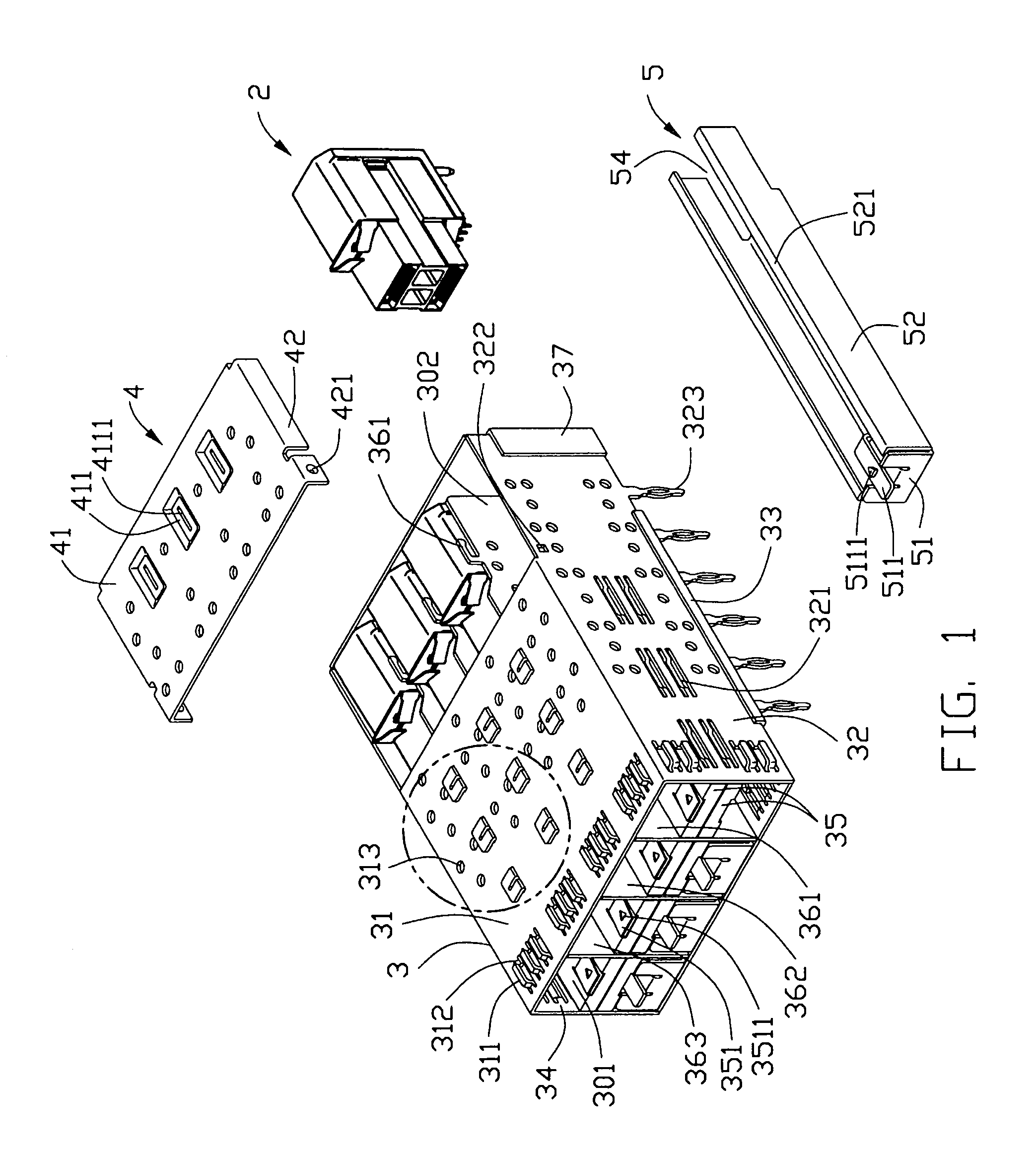
[0021]Referring to FIG. 1, a connector module in accordance with a preferred embodiment of the present invention mounted on a printed circuit board (not shown) of a host system device, comprises a plurality of connectors 2, a substantially cubic shielding cage 3 for receiving said connectors 2, a removable shielding lid 4 covering on the top surface of the shielding cage 3, a plurality of signal converters (not shown) received in the shielding cage 3 or a plurality of retainers 5 received in the shielding cage 3 for retaining the connectors 2 during shipment and placement to the printed circuit board and acting as removable / replaceable dust covers after the connectors 2 placement before mounting the signal converts.

[0022]The shielding cage 3 is made by metal sheet and comprises a top and bottom walls 31, 33, a pair of sidewalls 32, 34, a front opening and a rear wall 37. The shielding cage ...


PUM


Abstract

A connector module for receiving a signal converter and electrically connecting the signal converter to a printed circuit board mounted within an electronic system. The connector module includes a conductive cage having a plurality of press-fit type pins and a shielding lid. The connector module further defines a top opening and a cavity with an opening on a bottom portion of the conductive cage for receiving the connector which electrically connecting with the signal converter. The shielding lid covers on the top opening. The connector comprises a plurality of contacts each having a press-fit end, said press-fit ends extending toward the printed circuit board and mounting therein.

Description

BACKGROUND OF THE INVENTION[0001]1. Field of the Invention[0002]The present invention relates to a connector module, and in particular to a connector module employed in an electronic device for transmitting / receiving high speed signals.[0003]2. Description of the Prior Art or Related Art[0004]A small form-factor pluggable transceiver (SFP transceiver) provides a link between an electronic transmission line and an optical transmission line as a bi-direction optical-electronic converter. The SFP transceiver is mounted on a printed circuit board of a host system device via a high-speed connector. Then SFP transceiver and the connector are received in an EMI (electromagnetic interference) cage to avoid being interfered with by outside or emit electromagnetic circumstance.[0005]Many designs of the EMI cages and connector modules (comprising a connector and a transceiver) have been introduced for better performance, such as EMI performance and so on. Another consideration for design shoul...

Claims


Application Information

Patent Timeline
Patent Type & Authority Patents(United States)
IPC IPC(8): H01R13/648H01R12/55
CPCH01R13/5213H05K9/0058H01R23/6873H01R13/665H01R13/6582H01R13/6594
Inventor KORSUNSKY, IOSIF R.YI, CHONG HUNBROWN, ROBERT W.JOHNSON, LEWIS R.SHIPE, JOANNE E.HARLAN, TOD M.EMENHEISER, RICHARD B.MALEHORN, RICHARD L.BLICHASZ, CHARLES CHUCKJUNTWAIT, ERIC
Owner HON HAI PRECISION IND CO LTD
Learn More