Eureka AIR delivers breakthrough ideas for toughest innovation challenges, trusted by R&D personnel around the world.

Modularized connector for computer

a computer and module technology, applied in the direction of electrical digital data processing, coupling device connections, instruments, etc., can solve the problems of affecting the performance of the computer, the connector that is mounted to the main board of the computer is not allowed to easily dismount from the main board, and the maintenance and repair is difficult for the general consumer, so as to achieve convenient mounting/disassembly and enhance the effect of emi performan

Inactive Publication Date: 2010-03-18
GOLDEN BRIDGE ELECTECH INC
View PDF4 Cites 10 Cited by
  • Summary
  • Abstract
  • Description
  • Claims
  • Application Information

AI Technical Summary

Benefits of technology

[0004]An objective of the present invention is to provide easy mounting / dismounting and enhanced EMI performance during the operation thereof.

Problems solved by technology

Although convenient connection with the external devices can be easily realized through the connectors exposed on the wall of the computer enclosure, yet the connectors that are mounted to the main board of the computer are not allowed to easily dismount from the main board.
Thus, when a connector is broken or fails to properly function, it is generally impossible for a regular computer user to replace the broken connector and the computer has to be returned to the factory for maintenance and repairing.
This makes the maintenance and repairing difficult for the general consumers.
Further, since the conventional connectors are often set in physical engagement with the computer enclosure, which is considered a grounding potential, with a metal censing thereof, the grounding area of the connectors is apparently very small and the impedance thereof cannot be enhanced, eventually leading to poor electromagnetic shielding and affecting electrical performance of the connectors.
Thus, the conventional electrical connectors provided for computers do not suit practical needs of using computers.

Method used


Image

  • Modularized connector for computer
  • Modularized connector for computer
  • Modularized connector for computer

Examples


Embodiment Construction

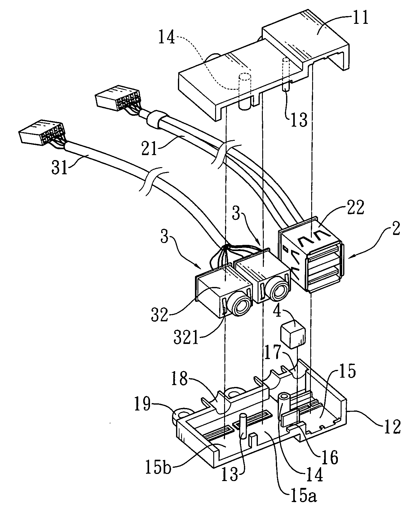
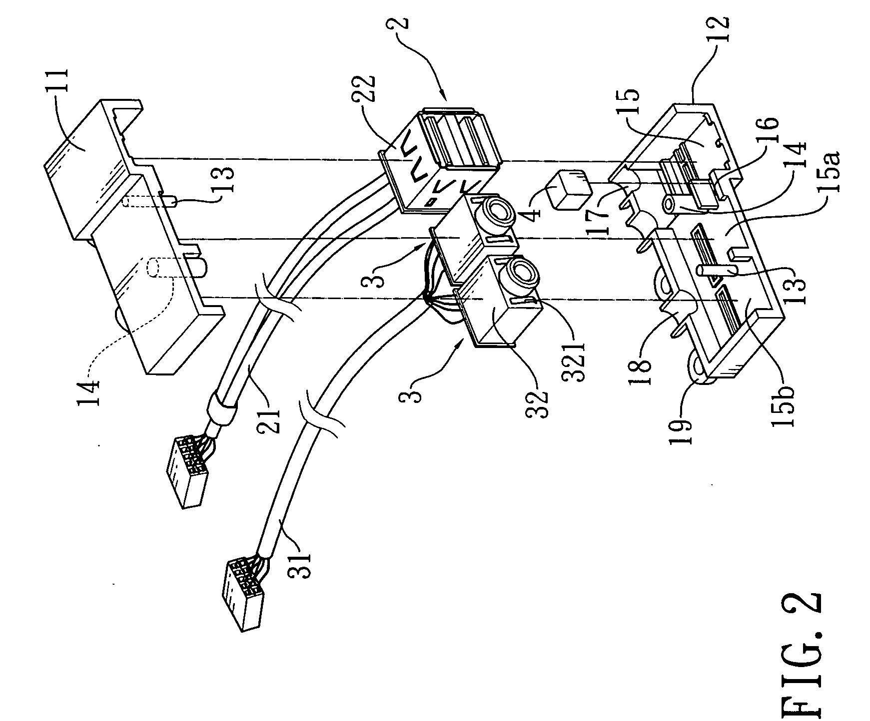
[0011]With reference to the drawings and in particular to FIGS. 1-3, which respectively show a perspective view, a front-side exploded view, and a rear-side exploded view of a modularized connector constructed in accordance with the present invention for a computer, as shown, the present invention provides a modularized connector for a computer, comprising a housing 1, a first connector 2, and at least two second connectors 3, and a conductor block 4.

[0012]The housing 1 is comprised of an upper member 11 and a lower member 12. The upper and lower members 11, 12 respectively form mated mounting poles 13 and holed projections 14. The housing 1 defines therein at bleast three receptacle chambers 15, 15a, 15b that are arranged in a juxtaposing manner and communicate an end face of the housing 1. The housing 1 has an end face forming a notch 16 communicating between at least two 15, 15a of the receptacle chambers. The housing 1 also has an opposite end face that forms wire retention sect...


PUM


Abstract

The present invention provides a modularized connector for a computer, including a housing forming at least three receptacle chambers and having an end face forming a notch and an opposite end face forming wire retention sections respectively communicating the receptacle chambers, and also forming mounting sections close to the wire retention sections; a first connector received in one of the receptacle chambers and having conductive connection wires extending through the respective wire retention section, the first connector being encased by a metal casing; second connectors respectively received in the remaining ones of the receptacle chambers and each having conductive connection wires extending through the respective wire retention section, each second connector being encased by a metal casing that has an end wall forming at least one resilient tab; and a conductor block arranged in the notch and having opposite side faces in physical engagement with the metal casings of the first and second connectors that juxtapose each other. The modularized connector features easy mounting / dismounting and enhanced EMI performance.

Description

FIELD OF THE INVENTION[0001]The present invention relates to a modularized connector for a computer, and in particular to a modularized connector featuring easy mounting / dismounting and enhanced EMI (electromagnetic interference) performance.BACKGROUND OF THE INVENTION[0002]A computer device is often equipped with connectors for connection external devices. Such connectors can be mounted to an edge of a main board in such a way that mating surfaces or openings of the connectors are exposed through a wall of the computer enclosure to allow plugging of the external devices to the connectors on the wall of the computer enclosure for expansion of the hardware and functionality of the computer in a convenient manner.[0003]Although convenient connection with the external devices can be easily realized through the connectors exposed on the wall of the computer enclosure, yet the connectors that are mounted to the main board of the computer are not allowed to easily dismount from the main b...

Claims


Application Information

Patent Timeline
Patent Type & Authority Applications(United States)
IPC IPC(8): H01R13/514
CPCG06F2200/1631H01R13/514H01R2201/06H01R27/02H01R13/65802H01R13/6582
Inventor CHOU, CHUN-CHI
Owner GOLDEN BRIDGE ELECTECH INC
Why Eureka
Eureka Blog
Learn More