
Elvator controlled cabinet

A technology for elevator control and control cabinets, applied in elevators, transportation and packaging, etc., which can solve problems such as large inspection area, ground potential cannot be quickly stabilized, and poor electrical conductivity

Inactive Publication Date: 2007-11-28
TOSHIBA ELEVATOR KK
View PDF0 Cites 9 Cited by
  • Summary
  • Abstract
  • Description
  • Claims
  • Application Information

AI Technical Summary

Problems solved by technology

Due to the two-sided inspection method, an inspection area needs to be reserved at the front and back of the elevator control cabinet, and the choice of installation location is more restricted, and the required inspection area is relatively large.
[0007] In addition, in order to improve the corrosion resistance of the elevator control cabinet, the existing elevator control cabinet is usually sprayed with insulating paint or other coatings with poor conductivity on the surface of the iron cabinet.
However, spraying insulating paint will affect the performance of the elevator control cabinet against electromagnetic interference. After the surface of such an elevator control cabinet is insulated, when the cabinet is subjected to sudden electromagnetic interference, it will not have good electrical continuity. Ground potential does not stabilize quickly

Method used


Image

  • Elvator controlled cabinet
  • Elvator controlled cabinet
  • Elvator controlled cabinet

Examples


Embodiment 1

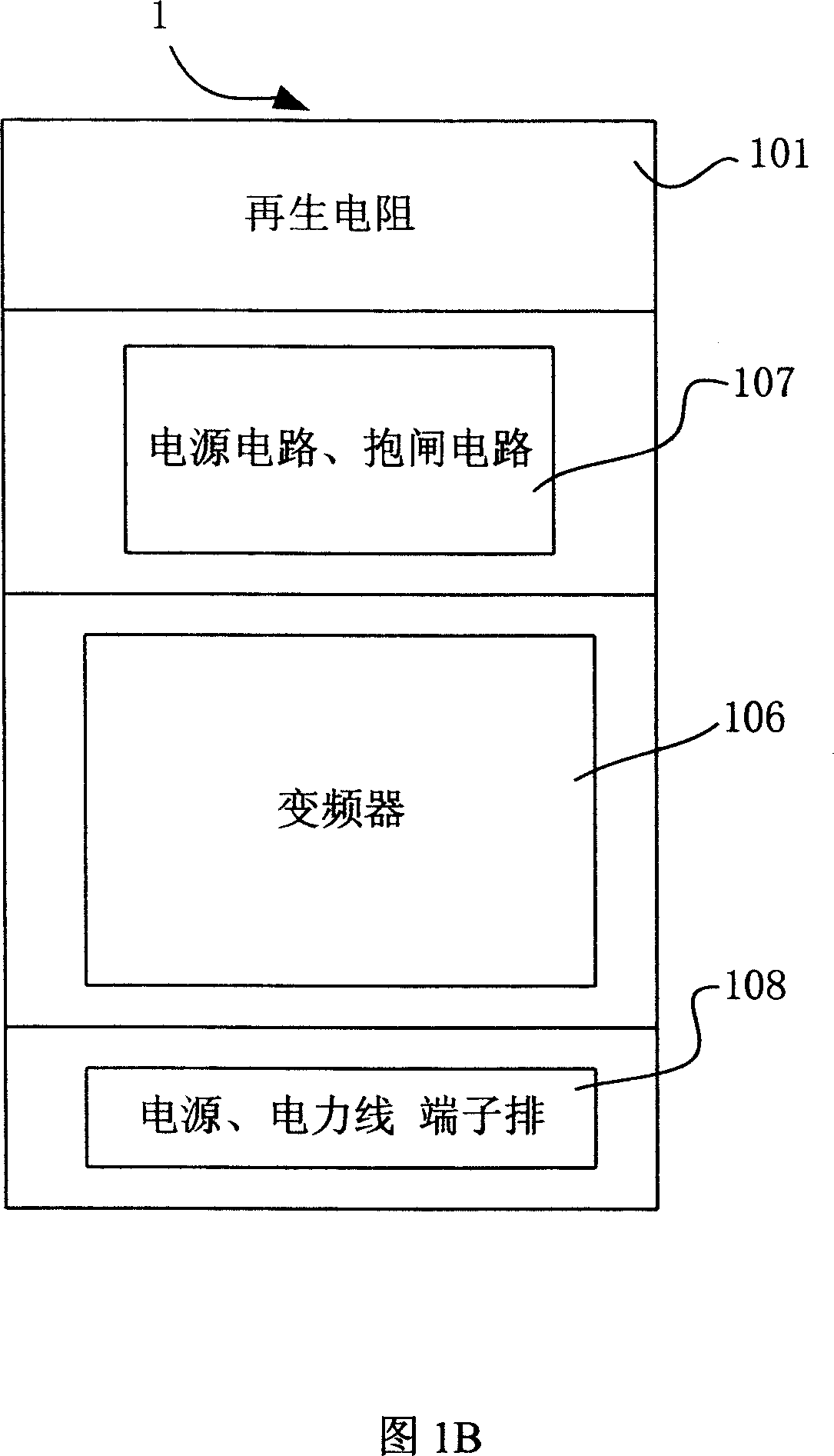
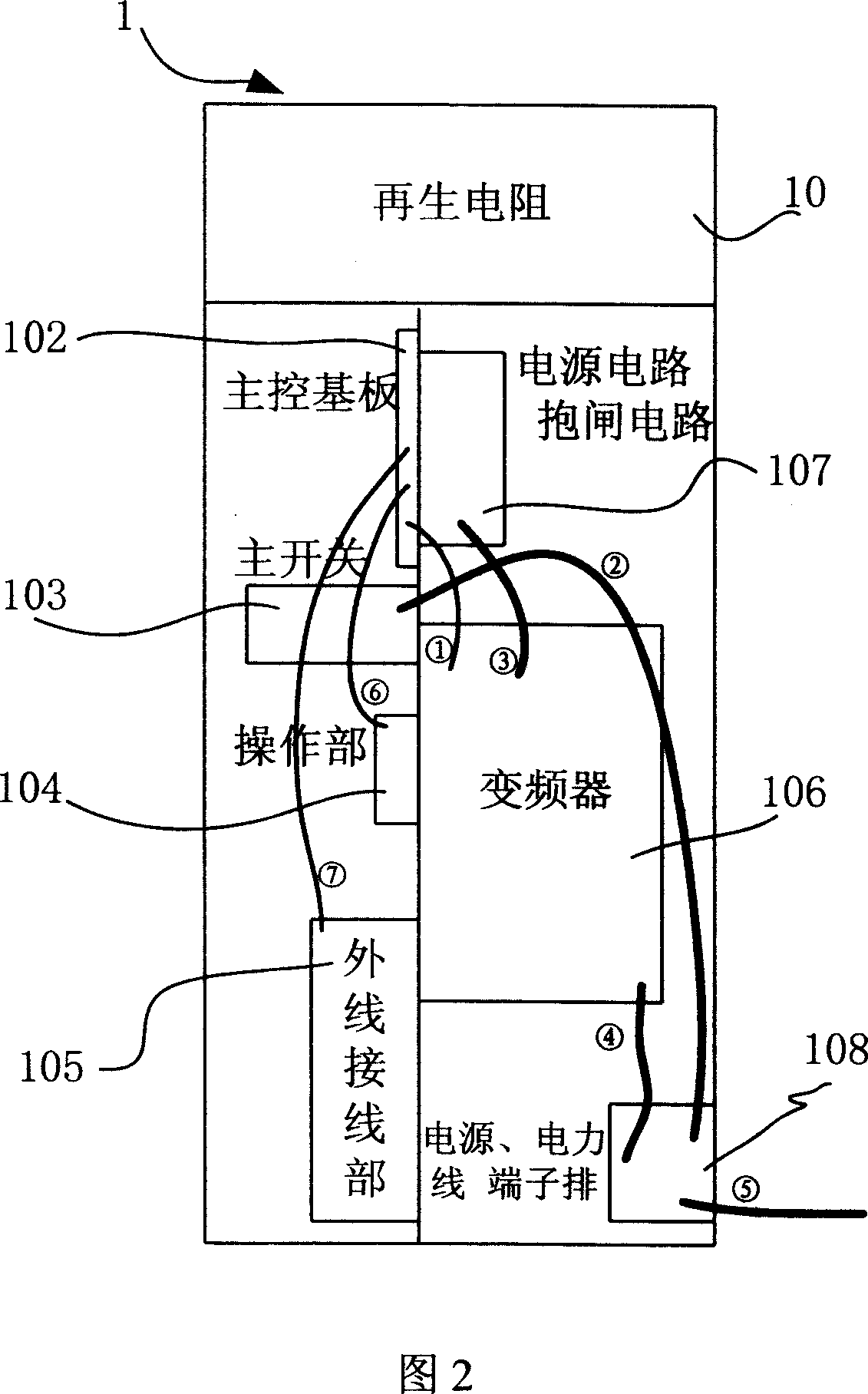
[0017] The technical solution of Embodiment 1 of the present invention will be specifically described below with reference to FIG. 3 . Fig. 3 is a schematic diagram of the main components of the elevator control cabinet according to the first embodiment of the present invention, and is also a front view of the elevator control cabinet according to the first embodiment. Compared with the existing elevator control cabinet, the solution of the first embodiment does not require any circuit modification or addition or deletion of components. It can be seen from Fig. 3 that the main difference between the solution of Embodiment 1 and the existing elevator control cabinet is that the main circuit unit 11 and the control circuit unit 12 in Embodiment 1 are separated from each other, and are respectively arranged in the elevator control cabinet 1. In the two spaces arranged left and right, the two spaces are isolated by the shielding layer 13 to prevent electrical and / or magnetic inter...

Embodiment 2

[0026] The elevator control cabinet of this embodiment is basically the same as that of Embodiment 1, the difference is that the surface of the elevator control cabinet of this embodiment is plated with good conductive materials, such as zinc, copper, gold, silver and the like. From the perspective of cost performance and process realization, it is better to choose galvanized. The existing elevator control cabinet is sprayed with insulating paint, which will affect the performance of the elevator control cabinet against electromagnetic interference. This is because the existing elevator control cabinet is made of materials with insufficient conductivity such as iron. When subjected to sudden electromagnetic interference, it cannot quickly return to the ground potential, so that the ground potential cannot be quickly stabilized. If the surface of the elevator control cabinet is plated with a good conductive material, and the conductivity of the good conductive material is highe...


PUM


Abstract

The lift control cabinet includes one main circuit unit and one control circuit unit set separately in two magnetically isolated rooms inside the lift control cabinet. The said configuration can minimize the electromagnetic interference of the main circuit unit on the control circuit unit, so as to reduce error detection rate of the control signal and malfunctions. In addition, the lift control cabinet has all the electric elements single-side mounted and thus easy overhaul and lowered maintenance cost, and the surface of the lift control cabinet is covered with plated conductive material, rather than insulating material, and thus has excellent shield effect.

Description

technical field [0001] The invention relates to an elevator control cabinet. Background technique [0002] The elevator control cabinet is composed of two circuit units, namely the main circuit unit and the control circuit unit. Among them, the main circuit unit is mainly used to provide electric power for the elevator, and includes a high-current circuit that drives the motor of the main engine of the elevator. The control circuit unit is mainly used to process the start, deceleration, and stop of the elevator drive machine and door machine, as well as the door switch, operation mode, floor display, call, safety protection and other signals. It is composed of a weak current circuit. Operation, to realize the control of the elevator. [0003] In the existing elevator control cabinet, all the wiring of the main circuit unit and the control circuit unit are arranged in the whole elevator control cabinet, and are arranged in a staggered manner with...

Claims


Application Information

Patent Timeline
IPC IPC(8): B66B1/34
Inventor 张云强菊池宽
Owner TOSHIBA ELEVATOR KK
Learn More