
Connector shielding apparatus and methods

a shielding apparatus and shielding technology, applied in the direction of coupling protective earth/shield arrangement, coupling device connection, manufacturing tools, etc., can solve the problems of high cost demands of the telecommunications industry, unsuitable for ever-increasing data rates, and high restrictions on the mechanical design of shields, so as to improve the emi performance of the connector assembly and minimize costs.

Active Publication Date: 2012-05-22
CANTOR FITZGERALD SECURITIES
View PDF28 Cites 10 Cited by
  • Summary
  • Abstract
  • Description
  • Claims
  • Application Information

AI Technical Summary

Benefits of technology

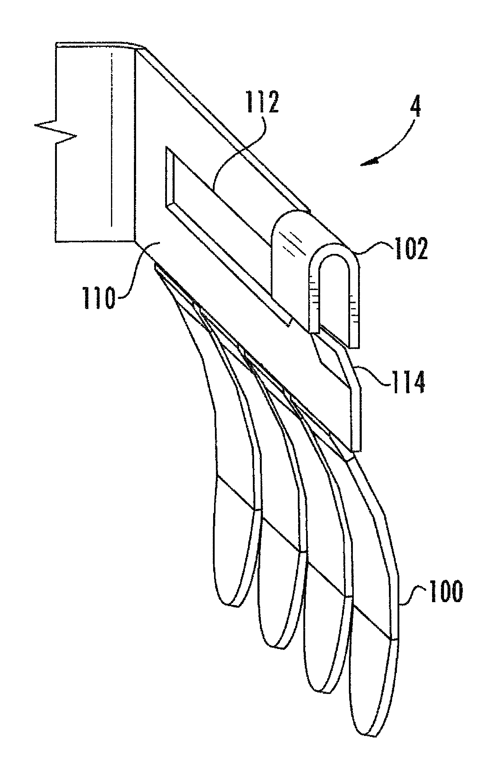
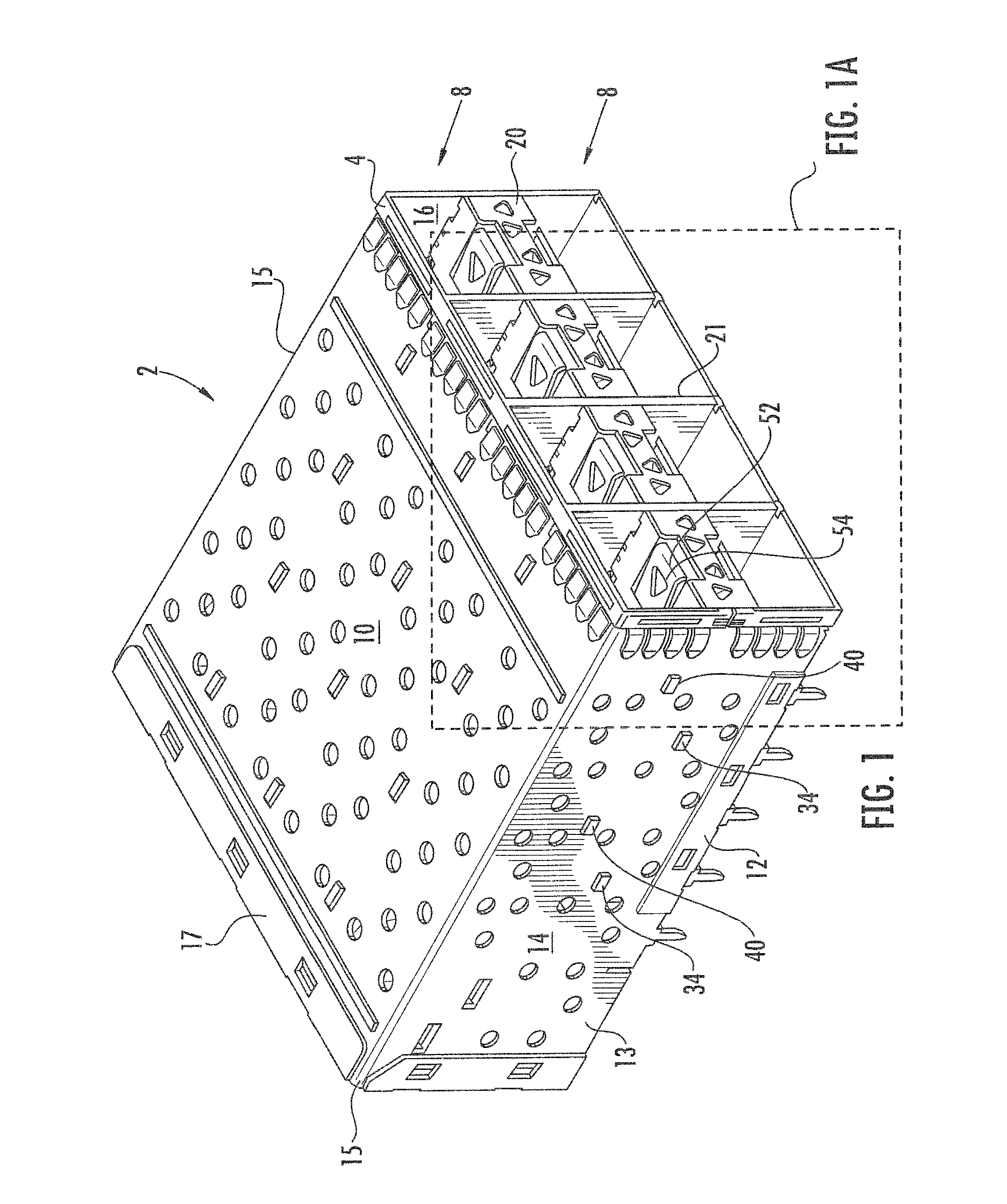
[0011]The present invention fulfills the foregoing needs by providing, inter alia, novel features that improve the EMI performance of the connector assembly while minimizing costs.
[0018]In a seventh aspect of the invention, a method of doing business is disclosed. In one embodiment, the method comprises providing a connector cage assembly comprising a first configuration and further comprising a plurality of assembly features for adapting the connector cage assembly to a second configuration; inserting an EMI shield member into the plurality of assembly features thereby assembling the second configuration for the connector cage assembly wherein costs are reduced by virtue of the connector cage assembly comprising first and second configurations.

Problems solved by technology

Although conventional pluggable designs have been used successfully in the past, they have tended to be unsuitable for ever-increasing data rates in combination with the cost demands of the telecommunications industry.
However, telecommunications standards such as SFP+ are highly restrictive with regards to the mechanical design of the shield.

Method used


Image

  • Connector shielding apparatus and methods
  • Connector shielding apparatus and methods
  • Connector shielding apparatus and methods

Examples


Embodiment Construction

[0040]Reference is now made to the drawings wherein like numerals refer to like parts throughout.

[0041]As used herein, the term “integrated circuit (IC)” refers to without limitation any type of device, whether single or multiple die, having any level of integration (including without limitation ULSI, VLSI, and LSI) and irrespective of process or base materials (including, without limitation Si, SiGe, CMOS and GaAs). ICs may include, for example, memory devices (e.g., DRAM, SRAM, DDRAM, EEPROM / Flash, ROM), digital processors, SoC devices, FPGAs, ASICs, ADCs, DACs, transceivers, memory controllers, and other devices, as well as any combinations thereof.

[0042]As used herein, the term “memory” includes any type of integrated circuit or other storage device adapted for storing digital data including, without limitation, ROM. PROM, EEPROM, DRAM, SDRAM, DDR / 2 SDRAM, EDO / FPMS, RLDRAM, SRAM, “flash” memory (e.g., NAND / NOR), and PSRAM.

[0043]As used herein, the term “digital processor” is mea...


PUM

PropertyMeasurementUnit
speedaaaaaaaaaa
sizeaaaaaaaaaa
densityaaaaaaaaaa

Abstract

An electrical connector assembly having shielded cage assembly with at least one port for receiving modules, and methods of manufacture and use thereof. In one embodiment, the modules comprise SFP-type (small form-factor pluggable) modules, and the shielded cage assembly comprises an EMI shield member that is disposed at a port opening for the electrical connector assembly. In one variant, the EMI shield member can be disposed on the electrical connector cage assembly without the need for secondary processing techniques such as soldering, or resistance welding. This is accomplished via for example the utilization of mechanical snap features.

Description

PRIORITY AND RELATED APPLICATIONS[0001]This application claims priority to U.S. Provisional Patent Application Ser. No. 61 / 201,460 filed Dec. 11, 2008 entitled “Connector Shielding Apparatus And Methods”, which is incorporated herein by reference in its entirety. This application is also generally related to the subject matter of co-pending U.S. patent application Ser. No. 12 / 011,796 filed Jan. 29, 2008 and entitled “Low-Profile Connector Assembly and Methods” which claims priority to U.S. Provisional Patent Application Ser. No. 60 / 898,677 filed Jan. 30, 2007 of the same title, and to U.S. Provisional Patent Application Ser. No. 61 / 010,318 filed Jan. 4, 2008 and entitled “Heterogeneous Connector Apparatus and Methods of Manufacture (SFP over RJ)”, each of the foregoing incorporated herein by reference in its entirety.COPYRIGHT[0002]A portion of the disclosure of this patent document contains material that is subject to copyright protection. The copyright owner has no objection to th...

Claims


Application Information

Patent Timeline
Patent Type & Authority Patents(United States)
IPC IPC(8): H01R9/03
CPCH01R23/6873H01R43/18H01R13/659H01R13/6594Y10S439/939Y10T29/49826Y10S439/927
Inventor TSOU, CHENG JUNG
Owner CANTOR FITZGERALD SECURITIES
Learn More