
Modular connector plug having a wire guide filter with an impedance containing portion and a cable guide portion

a module connector and filter technology, applied in the direction of coupling device details, coupling device connection, coupling protective earth/shielding arrangement, etc., can solve the problems of not meeting such levels consistently, containing more components, and being more expensive to manufacture and assemble, so as to achieve easy and economical manufacture and easy to apply

Active Publication Date: 2011-10-11
BEL FUSE MACAO COMML OFFSHORE
View PDF15 Cites 10 Cited by
  • Summary
  • Abstract
  • Description
  • Claims
  • Application Information

AI Technical Summary

Benefits of technology

[0012]Still another object of the present invention to provide new and improved modular connector plugs for data transmission at speeds from 100 to 500 MHz which are easy and economical to manufacture using conventional methods and equipment.
[0013]Yet another object of the present invention is to provide new and improved modular connector plugs for data transmission at speeds from 100 to 500 MHz which are easy to apply to cables with consistent repeatable performance.
[0014]A further object of the present invention is to provide new and improved modular connector plugs for data transmission at speeds from 100 to 500 MHz which are able to terminate a wide variety of cables of varying construction and manufacture.
[0016]Another object of the present invention to provide new and improved modular connector plugs for data transmission at speeds from 100 to 500 MHz which also provide improved EMI performance with both a shielded and unshielded modular connector.
[0024]A load bar may be employed forwardly of the wire guide filter to precisely position the cable conductors in alignment with respective plug contacts.

Problems solved by technology

While this design may achieve category 5e or 6 levels, it will not meet such levels consistently and will rarely meet Category 6A performance requirements.
More complex plug designs incorporate printed circuit boards that are used to rout the signals.
These designs contain more components and are more expensive to manufacture and assemble.
This design can meet CAT 6A, but is very expensive.
There are no designs known that would improve the EMI performance when mated with unshielded jacks.

Method used


Image

  • Modular connector plug having a wire guide filter with an impedance containing portion and a cable guide portion
  • Modular connector plug having a wire guide filter with an impedance containing portion and a cable guide portion
  • Modular connector plug having a wire guide filter with an impedance containing portion and a cable guide portion

Examples


Embodiment Construction

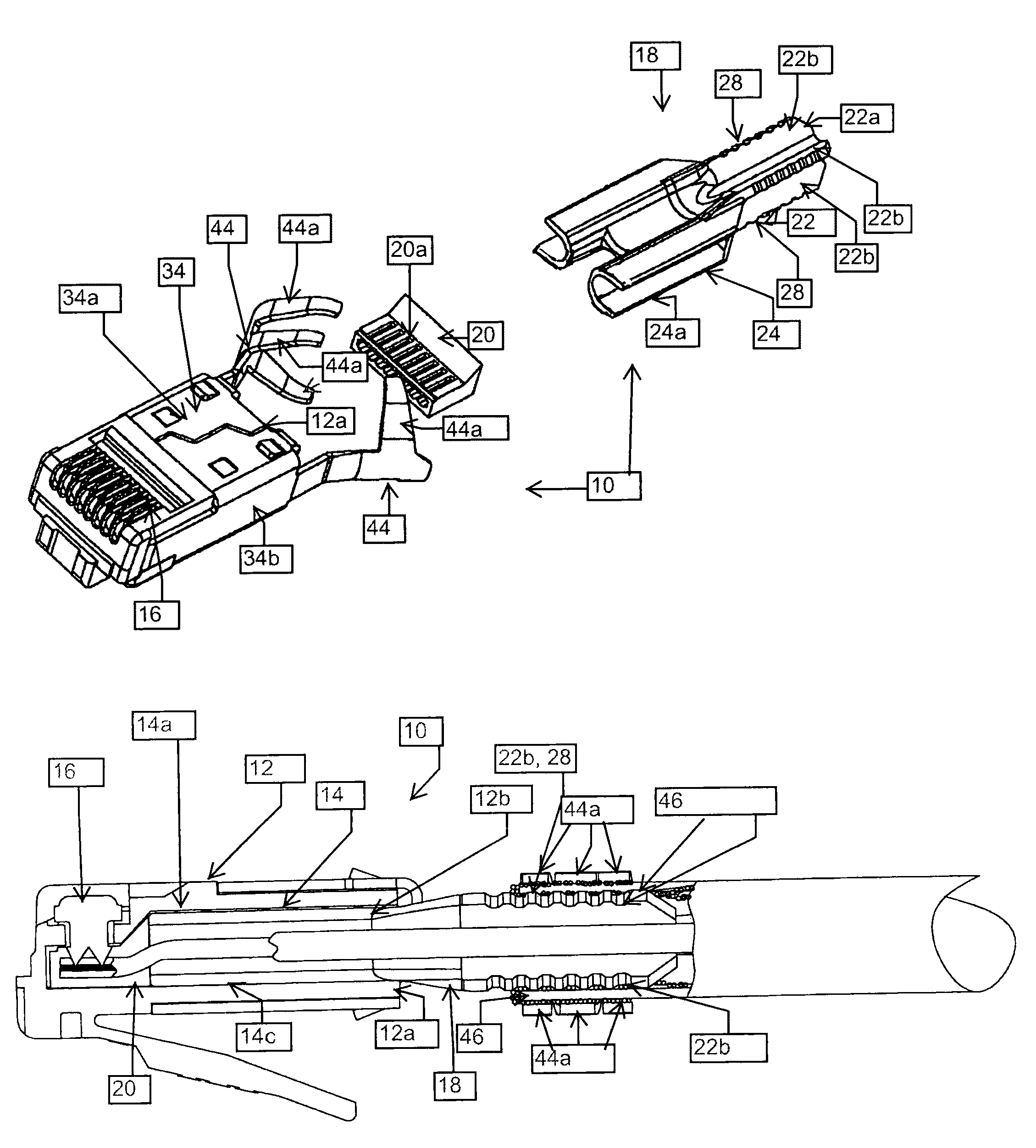
[0036]Referring now to the drawings wherein like reference characters designate identical or corresponding parts throughout the several views, and more particularly to FIGS. 1, 5 and 6, an embodiment of a modular connector plug in accordance with the invention, designated 10, comprises a housing 12 formed of insulative material, such as plastic, having a longitudinally extending conductor-receiving cavity 14 (see FIGS. 5 and 6) formed therein opening onto a rear surface 12a of the housing 12. A plurality of contacts 16, formed of metallic material such as copper alloy or stainless steel, are situated in a forward region of the housing 12. A wire guide filter 18 is at least partially situated in the conductor-receiving cavity 14 through an opening 12b (FIG. 6) at the rear surface 12a of the housing 12 (see FIGS. 5 and 6). A load bar 20 is situated in the conductor-receiving cavity 14 forwardly of the wire-guide filter 18 for accurately aligning the cable conductors with respective co...


PUM


Abstract

A modular connector plug for high speed applications includes a wire guide filter at least partially situated in the conductor-receiving cavity of the housing of the plug. The wire guide filter includes an impedance containing portion comprising a longitudinally extending body having a plurality of longitudinally extending passageways and an internal cable guide portion comprising a longitudinally extending body defining a plurality of longitudinally extending passageways.

Description

RELATED APPLICATIONS[0001]This application claims the priority filing date of U.S. Provisional Application Ser. No. 61 / 280,401 filed Nov. 3, 2009.FIELD OF THE INVENTION[0002]This invention relates generally to modular connectors and, more particularly, to modular connector plugs for high speed applications.BACKGROUND OF THE INVENTION[0003]The speed of data transmission has increased. New specifications for the performance of modular plugs and jacks reflect the need for higher speed transmission without signal degradation. RJ45 modular plugs and jacks, not originally designed to perform at these levels, must be redesigned to meet the new, ever-increasing performance requirements based on existing infrastructure. While the outline and dimensions of the modular connectors are subject to the U.S. and international standards such as IEC 60603-7 series and TIA 568 series, the internal designs of plugs differ widely. The internal designs are intended to make the plugs satisfy the high spee...

Claims


Application Information

Patent Timeline
Patent Type & Authority Patents(United States)
IPC IPC(8): H01R13/66
CPCH01R9/034H01R13/719H01R13/6589H01R24/64H01R13/65914
Inventor GUTTER, DAVID HENRYALLISON, JENNIFERBELOPOLSKY, YAKOVCARTWRIGHT, JASONMAROWSKY, RICHARD D.
Owner BEL FUSE MACAO COMML OFFSHORE
Learn More