
Insole for a ballet slipper

a technology for ballet slippers and insoles, which is applied in the direction of uppers, bootlegs, stiffners, etc., can solve the problems of no intermediate articulation, no ballet slippers available on the market or in the patent literature that allow intermediate articulation, and children's difficulties in going from the flat position to the on pointe position

Inactive Publication Date: 2010-07-29
KARL MARGARET
View PDF10 Cites 33 Cited by
  • Summary
  • Abstract
  • Description
  • Claims
  • Application Information

AI Technical Summary

Benefits of technology

[0008]The primary object of the invention is to provide a ballet pointe shoe insole that allows a ballet dancer to practice dancing on pointe by progressing through a series of intermediate positions before achieving full pointe position.
[0009]Another object of the invention is to provide a pointe shoe sole whose sole combines the qualities of rigidity and flexibility where needed.
[0010]Another object of the invention is to provide a pointe shoe sole that is easy and economical to manufacture.
[0011]A further object of the invention is to provide a pointe shoe sole that has more durability and lasts longer than standard pointe shoes.

Problems solved by technology

Although this rigidity does help the dancer stay on point, there is a deficiency in the prior art in that novice dancers, especially children have a difficult time going from the flat position to the on pointe position without any intermediate articulation of the foot.
Due to the rigid construction of the insole, no intermediate articulation is possible.
Currently, there are no ballet slippers available on the market or in the patent literature that allow a student to roll through, that is, to rise or descend through demi-pointe comfortably.
Because of this, many young dancers suffer foot injuries during their attempts to dance on pointe.

Method used


Image

  • Insole for a ballet slipper
  • Insole for a ballet slipper
  • Insole for a ballet slipper

Examples


Embodiment Construction

[0024]Detailed descriptions of the preferred embodiment are provided herein. It is to be understood, however, that the present invention may be embodied in various forms. Therefore, specific details disclosed herein are not to be interpreted as limiting, but rather as a basis for the claims and as a representative basis for teaching one skilled in the art to employ the present invention in virtually any appropriately detailed system, structure or manner.

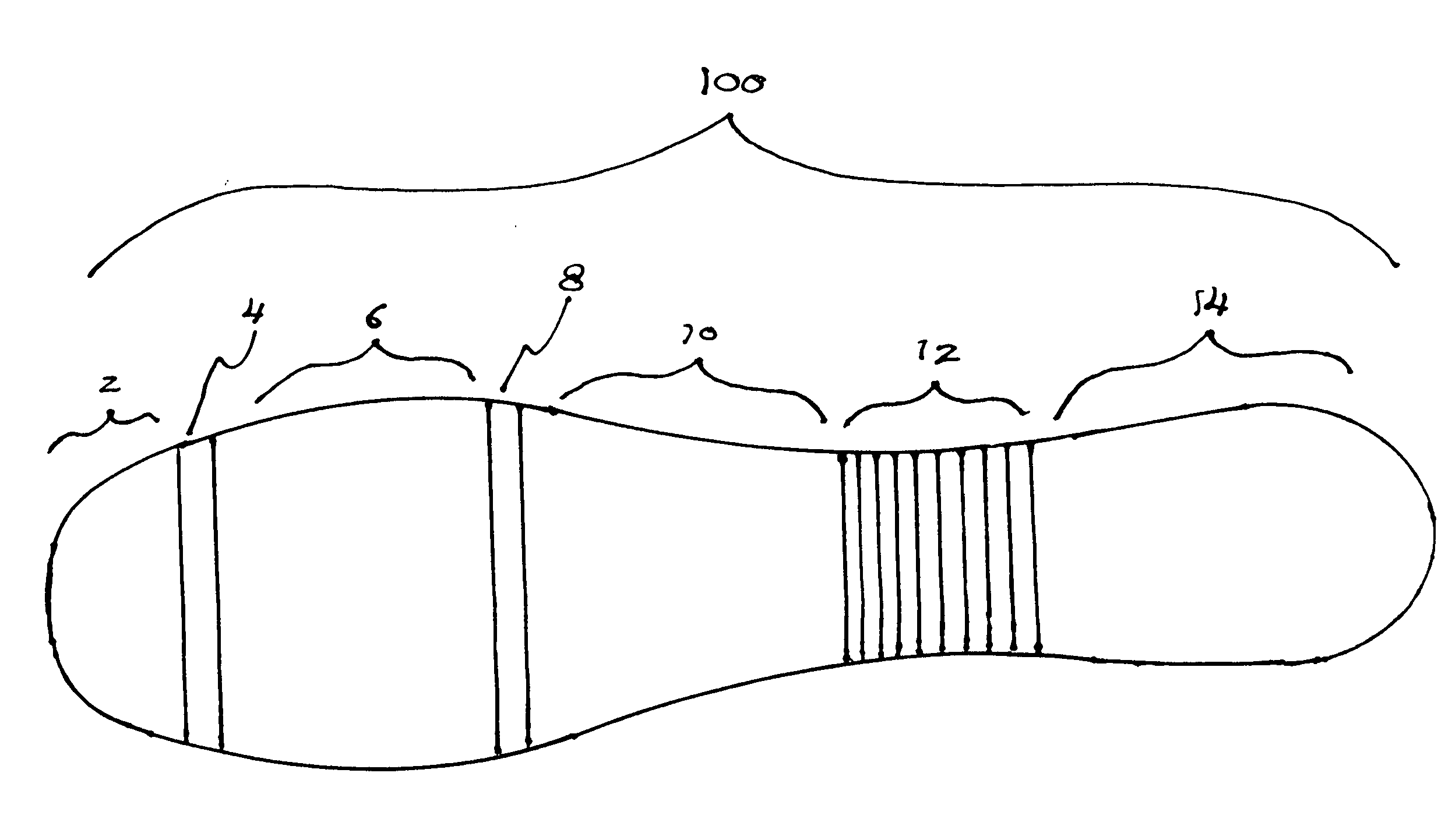
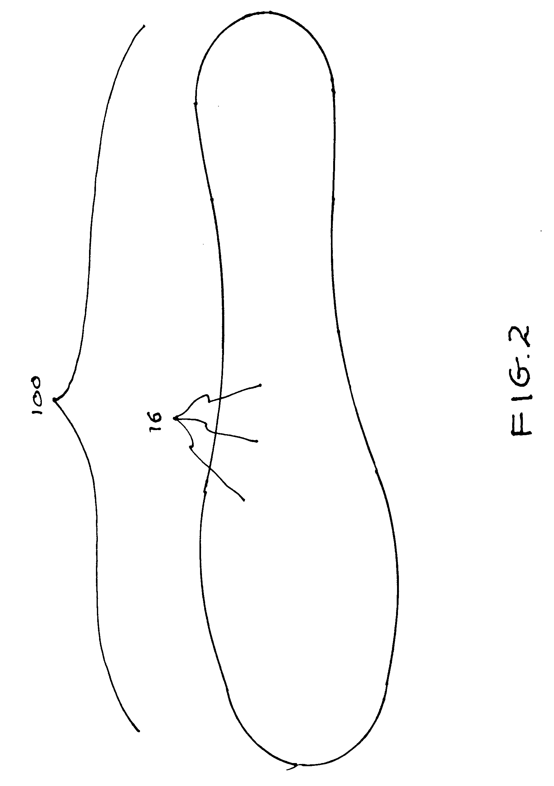
[0025]Referring now to FIG. 1 we see a plan view of the bottom of the insole for ballet slippers of the present invention 100. The overall shape conforms generally to the perimeter of a human foot. However, it should be noted that standard ballet shoes are not specifically designed for a right foot and a left foot. This view shows the insole broken up into specific segments. Segments 2, 4, 10 and 14 are rigid in construction. First segment 2 is a rigid segment located at the Distal Phalanges region of the foot. First rib 4 is flexibl...


PUM


Abstract

A point shoe insole for a ballet slipper with a two layered co-molded plastic sheet having a top layer made of semi-rigid plastic and a bottom layer made of four of rigid plastic members. The top sheet has a plurality of horizontally and downwardly facing ribs. The first and second downwardly facing ribs fit tightly between the first, second and third rigid plastic members of the bottom sheet. A third set downwardly facing ribs are located between the third rigid portion and the forth rigid portion. The area above the first and second downwardly facing ribs form hinges that allow the first, second and third rigid members to flex in an upward direction during the progression of movement of a user's foot between a flat plane and on pointe, but does not allow the first, second and third rigid members to flex in the opposite direction when the user's foot is on pointe.

Description

CROSS REFERENCE TO RELATED APPLICATIONS [0001]Not ApplicableSTATEMENT REGARDING FEDERALLY SPONSORED RESEARCH OR DEVELOPMENT [0002]Not ApplicableDESCRIPTION OF ATTACHED APPENDIX [0003]Not ApplicableBACKGROUND OF THE INVENTION [0004]This invention relates generally to the field of dance shoes and more specifically to an insole for a ballet slipper.[0005]Ballet shoes that allow a dancer to dance on pointe, that is, on the tip of their toes, have been in existence for approximately two hundred years. Ballet shoes that allow a dancer to dance on pointe have a rigid box shape at the tip of the shoe that allows the dancer to dance while his or her toes are pointed downward toward the floor. The insole of a standard ballet slipper tends to be rather rigid at the front and middle portion of the shoe to help support the dancer's foot while on pointe.[0006]Although this rigidity does help the dancer stay on point, there is a deficiency in the prior art in that novice dancers, especially childr...

Claims


Application Information

Patent Timeline
IPC IPC(8): A43B13/38
CPCA43B5/12A43B13/026A43B13/12A43B13/141
Inventor KARL, MARGARETSCRIBNER, GAREN P.
Owner KARL MARGARET
Learn More