Eureka AIR delivers breakthrough ideas for toughest innovation challenges, trusted by R&D personnel around the world.

Energy-free refrigeration door and method for making the same

a technology of refrigeration door and energy-free, which is applied in the field of refrigeration door, can solve the problems of high energy cost to the retailer, inability to see through the door, and energy cost over and beyond the energy cost of the cooling system, so as to reduce condensation on the glass, burden the cooling system, and increase energy cos

Inactive Publication Date: 2011-04-21
AGC FLAT GLASS NORTH AMERICA INC
View PDF42 Cites 35 Cited by
  • Summary
  • Abstract
  • Description
  • Claims
  • Application Information

AI Technical Summary

Benefits of technology

[0021]Another key objective of the present invention is to provide a refrigeration door that does not employ electrical energy in order to reduce condensation on the glass.
[0022]Another key objective of the present invention is to provide a refrigeration door that controls condensation and that does not transfer significant heat to the interior of the freezer or refrigerator, thereby further burdening the cooling system and increasing energy costs.
[0023]Still another objective of the present invention is to provide a refrigeration door with condensation control that is easier and more economical to manufacture, operate, and maintain than the prior art refrigeration doors and systems.
[0024]Yet another objective of the present invention is to provide a refrigeration door with condensation control that is easier to design, operate, and maintain.
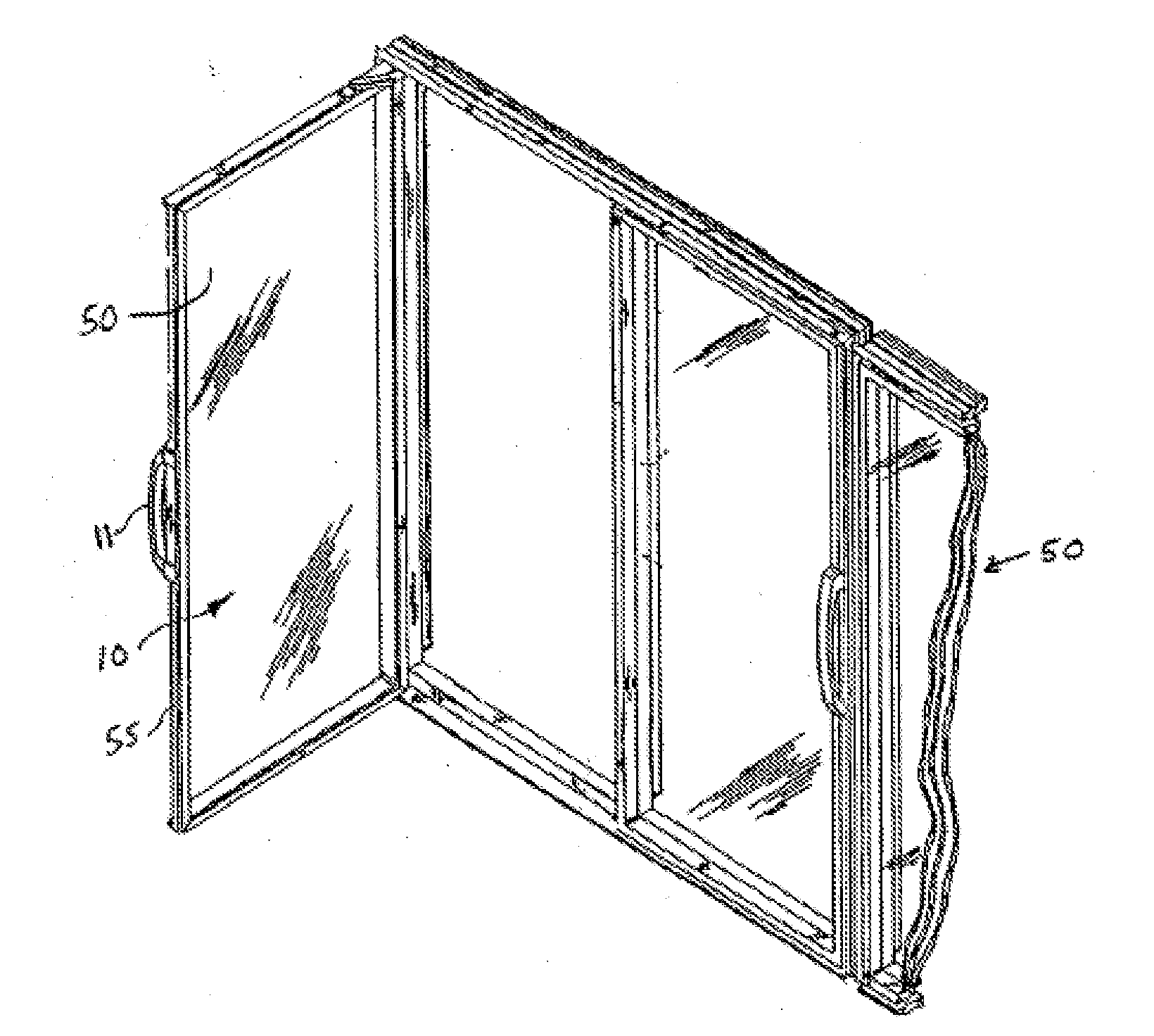
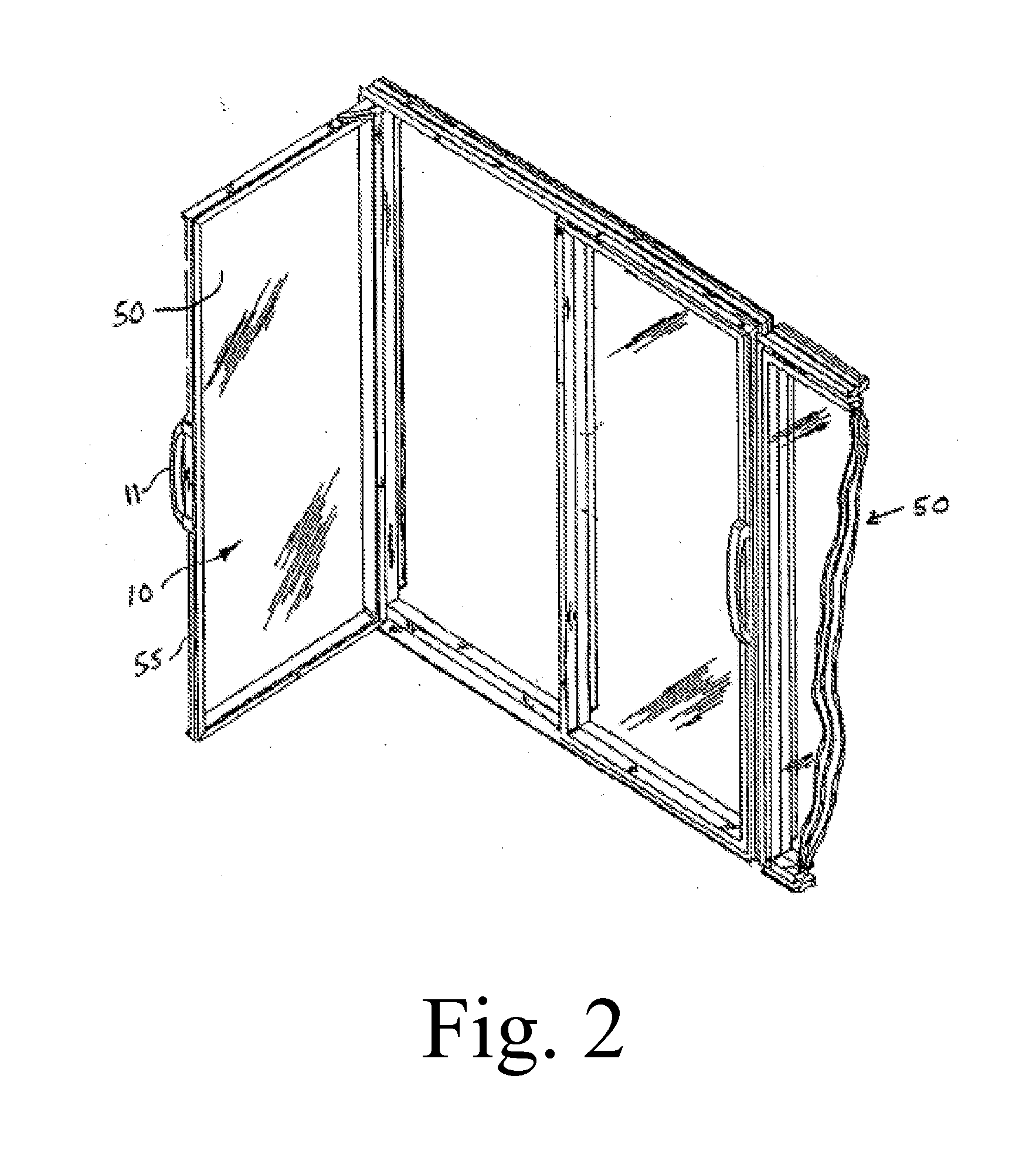
[0030]The present invention achieves these objectives and others by providing an energy-free refrigeration door, and method for making the same, comprising a door frame housing an insulating glass unit comprising inner, middle and outer sheets of glass. A first sealant assembly disposed around the periphery of the inner and middle sheets of glass forms a first chamber between the inner and middle sheets of glass. A second sealant assembly disposed around the periphery of the middle and outer sheets of glass forms a second chamber between the middle and outer sheets of glass. A gas, such as krypton, air, or argon is held in the first and second chambers. The outer sheet of glass and inner sheet of glass each have an unexposed surface that faces the middle sheet of glass. A low emissivity coating is disposed on the unexposed surfaces of the inner and outer sheets of glass so that the glass door as a whole has a U value that prevents formation of condensation on the outer surface of the outer sheet of the glass door, without the application of electricity to heat the door, while also providing the desired evaporation rate of condensation from the inner side of the inner sheet of the glass door.

Problems solved by technology

However, when condensation forms on the glass (sometimes referred to as“fogging”), the customer is not able to see through the door to identify the products inside, which is undesirable from the standpoint of the customer and the store owner or retailer as well.
Consequently, when condensation or frost is on the glass door, the customer must perform the unpleasant task of opening the refrigeration door to identify the contents inside, which is impractical in a store with a large number of freezers or refrigerators.
Not only is opening every refrigeration door tedious and time consuming from the customer's perspective, it is undesirable from the retailer's freezers and refrigerators, thereby resulting in higher energy costs to the retailer.
There are numerous drawbacks and problems associated with these conventional heated refrigeration doors of the prior art.
First, heating the door incurs an energy coast above and beyond the energy costs of the cooling system.
In a standard size commercial freezer, the additional cost to heat a freezer door is substantial—based on current electrical utility pricing, such additional costs can be $100 per year or more for each freezer.
Considering that many stores utilize multiple freezers, with some supermarkets and other food retailers utilizing hundreds of freezers, the cumulative energy costs associated with such heated freezer doors are significant.
Second, excess heat from conventional heated refrigeration doors will migrate to the refrigeration compartment, creating an additional burden on the cooling system, which results in still greater energy costs.
Third, if the power supplied to the door for heating is too low, is turned off, or is shut down due to a power outage, condensation and / or frost will form on the glass.
If the power dissipation is too high, unnecessary additional energy costs will be incurred.
In order to achieve the necessary precise control of the door heating system, an electrical control system is required, which results in increased design and manufacturing costs, as well as substantial operational and maintenance costs.
Fourth, these electrically heated glass doors present a safety hazard to customers and a potential risk of liability and exposure to retailers and refrigeration system manufacturers.
The shopping carts used by customers in stores are heavy and metal.
If the shopping cart strikes and breaks the glass door, electricity may be conducted through the car to the customer, which could cause serious injury or even death.
However, the refrigeration doors disclosed in these patents suffer from the previously described drawbacks and problems associated with all electrically heated refrigeration doors.
While low E coatings have been applied to IGUs used in refrigeration doors both with and without electrically heating the doors, such coatings and IGUs are not capable of controlling condensation and providing the required thermal insulation through the broad range of temperatures and environments in which such refrigeration doors are utilized without applying electricity to heat the doors.
More specifically, notwithstanding the use of such low E coatings, refrigeration doors that are not heated have failed to provide condensation control in applications in which the interior temperature of the refrigeration compartment is substantially near or below freezing.

Method used


Image

  • Energy-free refrigeration door and method for making the same
  • Energy-free refrigeration door and method for making the same
  • Energy-free refrigeration door and method for making the same

Examples


Embodiment Construction

[0038]In the following description, for purposes of explanation and not limitation, specific details are set forth, such as particular coatings, coating processes, sheet thicknesses, seal assemblies, number of sheets, sheet spacings, and methods for assembling the door, etc. in order to provide a thorough understanding of the present invention. However, it will be apparent to one skilled in the art that the present invention may be practiced in other embodiments that depart from these specific details. Detailed descriptions of well-known coatings, coating processes, sealant assemblies, and methods for assembling the door are omitted so as not to obscure the description of the present invention. For purposes of this description of the invention, terms such as external, internal, outer, and inner are descriptions from the perspective of the inside of the freezer or refrigerator compartment as is evident from the figures.

[0039]Testing, as well as computer modeling, has shown that a U v...


PUM

PropertyMeasurementUnit
temperatureaaaaaaaaaa
voltageaaaaaaaaaa

Abstract

The present invention provides a refrigeration door, and method for making the same, for controlling condensation, providing thermal insulation, with a desired amount of visible transmittance, without using electricity to heat the door. The energy-free refrigeration door of the present invention includes a door frame housing and an insulating glass unit comprising inner, middle and outer sheets of glass. A first sealant assembly disposed around the periphery of the inner and middle sheets of glass forms a first chamber between the inner and middle sheets of glass. A second sealant assembly disposed around the periphery of the middle and outer sheets of glass forms a second chamber between the middle and outer sheets of glass. A gas, such as krypton, air, or argon is held in the first and second chambers. The outer sheet of glass and inner sheet of glass each have an unexposed surface that faces the middle sheet of glass. A low emissivity coating is disposed on the unexposed surfaces of the inner and outer sheets of glass so that the glass door as a whole has a U value that prevents formation of condensation on the outer surface of the outer sheet of the glass door, without the application of electricity to heat the door, while also providing the desired evaporation rate of condensation from the inner side of the inner sheet of the glass door.

Description

CROSS-REFERENCE TO RELATED APPLICATIONS[0001]This application is a continuation of application Ser. No. 10 / 777,210, filed Feb. 13, 2004, which is a continuation of application Ser. No. 10 / 400,067, filed Mar. 27, 2003, which is a continuation of application Ser. No. 09 / 909,262, filed Jul. 19, 2001. Each of these applications is incorporated herein by reference in their entirety.BACKGROUND OF THE INVENTION[0002]1. Field of the Invention[0003]The present invention relates, generally, to refrigeration doors and, in particular, to an energy-free refrigeration door providing condensation control, thermal insulation, and a desired amount of visible transmittance. More particularly, the refrigeration door of the present invention achieves these desired characteristics through the application of a low-emissivity coating, without electrically heating the door. Throughout this application the term “refrigeration door” is meant to refer to a door used for freezers, refrigerators and similar uni...

Claims


Application Information

Patent Timeline
Patent Type & Authority Applications(United States)
IPC IPC(8): F25D23/02A47F3/04C03C27/06E06B3/67
CPCE06B3/6715A47F3/0434
Inventor CORDING, CHRISTOPHER R.
Owner AGC FLAT GLASS NORTH AMERICA INC
Why Eureka
Eureka Blog
Learn More