Single-segment linear constant-power LED (light-emitting diode) driving circuit and method
A technology of LED drive and constant power, which is applied in the field of single-segment linear constant power LED drive circuit, which can solve the problems of narrow input voltage range and low efficiency, and achieve the effect of the most simplified, high-efficiency, and highly integrated peripheral circuits
- Summary
- Abstract
- Description
- Claims
- Application Information
AI Technical Summary
Problems solved by technology
Method used
Image
Examples
Embodiment 1
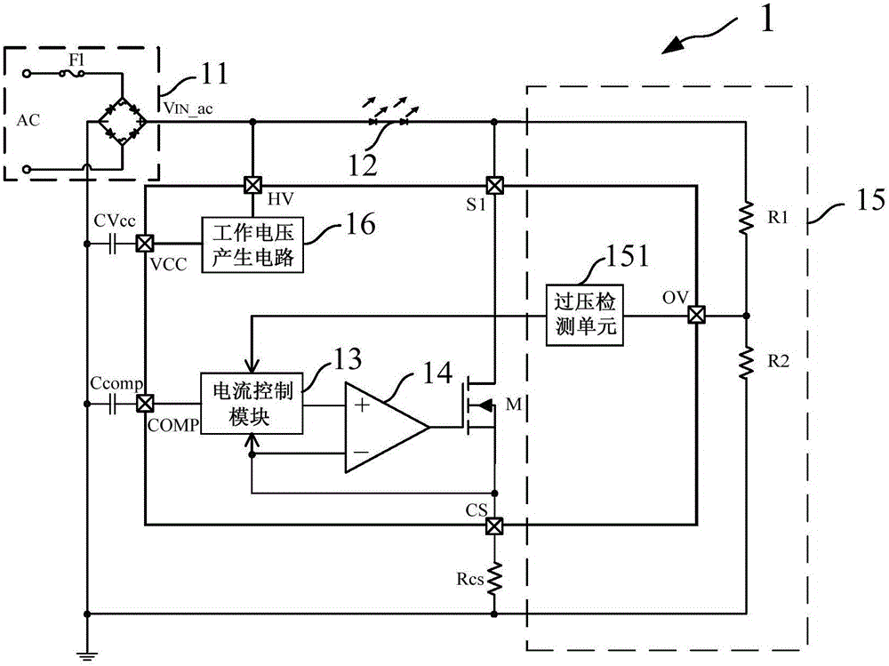
[0051] Such as figure 2 As shown, the present invention provides a single-segment linear constant power LED drive circuit 1, the single-segment linear constant power LED drive circuit 1 at least includes:
[0052] Voltage input module 11 , LED load 12 , power switch tube M, sampling resistor Rcs, current control module 13 , comparison module 14 , overvoltage control module 15 and working voltage generation circuit 16 .
[0053] Such as figure 2 As shown, the voltage input module 11 is used to provide the input voltage V IN _ac.
[0054] Specifically, such as figure 2 As shown, the voltage input module 11 is an external chip device, including an AC power supply AC, a fuse F1 and a rectification unit, the rectification unit includes two parallel diode groups, each diode group includes two diodes connected in series, The AC power supply AC is connected between two diodes of each diode group through the fuse F1, and the voltage input module 11 provides the input voltage V ...
Embodiment 2
[0070] Such as image 3 As shown, the present invention provides a single-segment linear constant power LED drive circuit, the structure of which is basically the same as that of Embodiment 1, the difference is that the overvoltage control module 15 also includes a constant current source I1 to adjust the current flow through The turn-off slope of the current of the LED load 12 further reduces electromagnetic interference and optimizes circuit performance.
[0071] Specifically, such as image 3 As shown, the overvoltage control module 15 includes a first resistor R1 , a second resistor R2 , a constant current source I1 and an overvoltage detection unit 151 . In this embodiment, the first resistor R1 and the second resistor R2 are external devices on the chip, and the constant current source I1 and the overvoltage detection unit 151 are on-chip devices. One end of the first resistor R1 is connected to the drain terminal S1 of the power switch tube M, the other end is connect...
PUM
 Abstract
Description
Claims
Application Information
 - Generate Ideas
- Intellectual Property
- Life Sciences
- Materials
- Tech Scout
- Unparalleled Data Quality
- Higher Quality Content
- 60% Fewer Hallucinations
Browse by: Latest US Patents, China's latest patents, Technical Efficacy Thesaurus, Application Domain, Technology Topic, Popular Technical Reports.
© 2025 PatSnap. All rights reserved.Legal|Privacy policy|Modern Slavery Act Transparency Statement|Sitemap|About US| Contact US: help@patsnap.com


