
Medicament vial having a heat-sealable cap, and apparatus and method for filling the vial

Inactive Publication Date: 2006-04-25
MEDINSTILL DEV
View PDF73 Cites 117 Cited by
  • Summary
  • Abstract
  • Description
  • Claims
  • Application Information

AI Technical Summary

Benefits of technology

[0011]Another aspect of the present invention is directed to a thermoplastic stopper defining a needle penetration region that is pierceable with a needle to form a needle aperture therethrough, and is heat resealable to hermetically seal the needle aperture by applying laser radiation at a predetermined wavelength and power thereto. The stopper includes a thermoplastic body defining a predetermined wall thickness in an axial direction thereof, and the thermoplastic body comprises: (i) a styrene block copolymer; (ii) an olefin; (iii) a predetermined amount of pigment that allows the body to substantially absorb laser radiation at the predetermined wavelength and substantially prevent the passage of radiation through the predetermined wall thickness thereof, and hermetically seal a needle aperture formed in the needle penetration region thereof in a predetermined time period of less than approximately 2 seconds; and (iv) a predetermined amount of lubricant that reduces friction forces at an interface of the needle and body during needle penetration thereof.
[0012]Another aspect of the present invention is directed to a thermoplastic stopper defining a needle penetration region that is pierceable with a needle to form a needle aperture therethrough, and is heat resealable to hermetically seal the needle aperture by applying laser radiation at a predetermined wavelength and power thereto. The stopper comprises a thermoplastic body defining a predetermined wall thickness in an axial direction thereof, and includes: (i) a first polymeric material in an amount within the range of about 80% to about 97% by weight and defining a first elongation; (ii) a second polymeric material in an amount within the range of about 3% to about 20% by weight and defining a second elongation that is less than the first elongation of the first material; (iii) a pigment in an mount that allows the body to substantially absorb laser radiation at the predetermined wavelength and substantially prevent the passage of radiation through the predetermined wall thickness thereof, and hermetically seal a needle aperture formed in the needle penetration region thereof in a predetermined time period of less than approximately 2 seconds; and (iv) a lubricant in an amount that reduces friction forces at an interface of the needle and body during needle penetration thereof.
[0015](ii) providing the thermoplastic stopper with a predetermined amount of pigment that allows the body to substantially absorb laser radiation at the predetermined wavelength and substantially prevent the passage of radiation through the predetermined wall thickness thereof;
[0019](vi) providing a lubricant at the interface of the needle and stopper to reduce friction forces therebetween;
[0022]One advantage of the apparatus and method of the present invention, is that the caps and locking members are secured to the vials prior to filling, thus enhancing the ability to maintain sterile conditions throughout the filling process and avoiding the need to assemble the vials in a sterile environment. As a result, the apparatus and method of the present invention significantly reduce processing time and cost in comparison to prior art vials and filling systems, and moreover, significantly increase the assurance of sterility throughout the assembly and filling processes.

Problems solved by technology

One of the drawbacks associated with such prior art dispensers, and processes and equipment for filling such dispensers, is that the filling process is time consuming, and the processes and equipment are expensive.
Further, the relatively complex nature of the filling processes and equipment can lead to more defectively filled dispensers than otherwise desired.
In many cases, there are complex assembly machines for assembling the vials or other dispensers that are located within the aseptic area of the filling machine that must be maintained sterile.
This type of machinery can be a significant source of unwanted particles.
In closed barrier systems, convection flow is inevitable and thus laminar flow, or substantially laminar flow, cannot be achieved.
When operation of an isolator is stopped, a media fill test may have to be performed which can last for several, if not many days, and can lead to repeated interruptions and significant reductions in production output for the pharmaceutical or other product manufacturer that is using the equipment.
In order to address such production issues, government-imposed regulations are becoming increasingly sophisticated and are further increasing the cost of already-expensive isolators and like filling equipment.
On the other hand, governmental price controls for injectables and vaccines, including, for example, preventative medicines, discourage such major financial investments.
One of the drawbacks associated with this approach, however, is that when the needle or like injection member is inserted through the cap and then withdrawn, it leaves a tiny hole in the cap.
However, the hole typically is not small enough to prevent air or other gases from passing through the hole and into the vial, and therefore such holes can allow the medicament to become contaminated or spoiled.
Certain preservatives, however, have been determined to cause undesirable effects on patients.
These preservative-free medicaments, and particularly preservative-free vaccines, are subject to contamination and / or spoilage if contained within a vial wherein the cap has a needle hole as described above.

Method used


Image

  • Medicament vial having a heat-sealable cap, and apparatus and method for filling the vial
  • Medicament vial having a heat-sealable cap, and apparatus and method for filling the vial
  • Medicament vial having a heat-sealable cap, and apparatus and method for filling the vial

Examples


Embodiment Construction

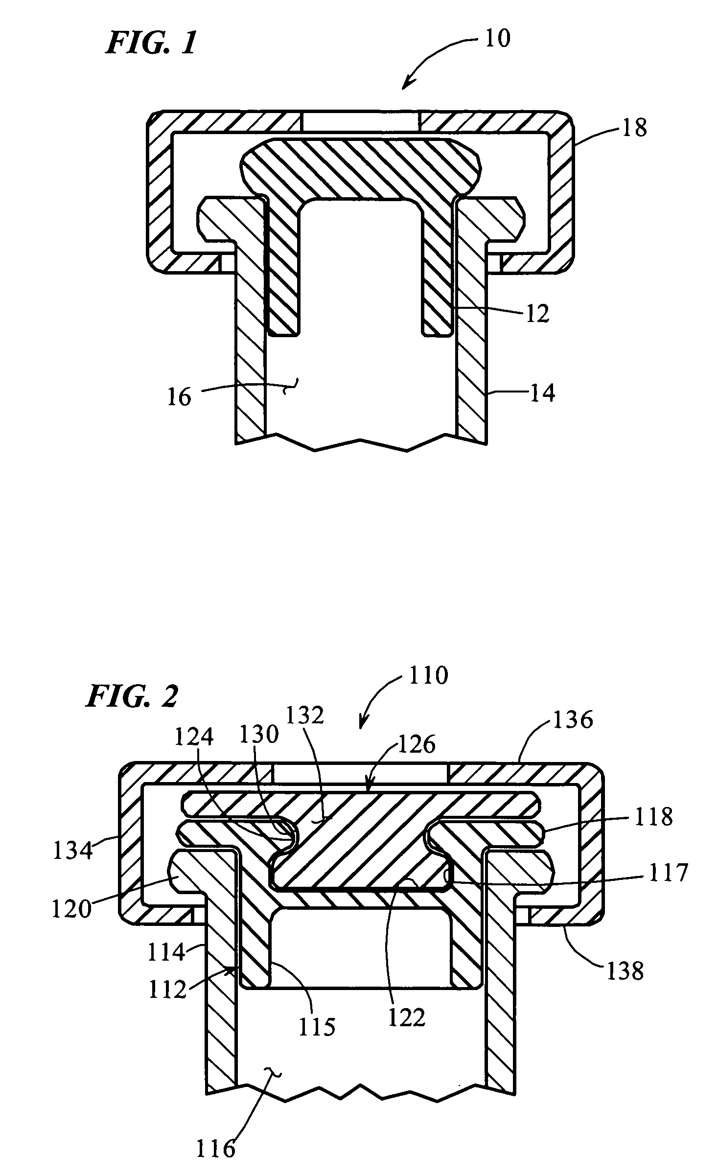
[0062]As shown in FIG. 1, a prior art cap for a medicament vial is generally designated by the reference numeral 10. The cap 10 includes a vulcanized rubber base 12, which is slidably received within the open end of a vial 14. The vial 14 is made of glass or like material, and it defines a chamber 16 for receiving medicament. An aluminum locking ring 18 surrounds the periphery of the cap 12 and vial 14, and it is crimped in place to lockably connect and seal the cap to the vial.

[0063]In operation, a hypodermic needle (not shown) is inserted through the vulcanized rubber base in order to deposit medicament within the chamber 16. Once the medicament has been deposited, the needle is withdrawn from the cap 10. Although the hole resulting from insertion of the needle will shrink somewhat from its maximum diameter due to the resiliency of the vulcanized rubber, the resultant hole is typically still large enough to pass gas or vapor and thereby compromise any preservative-free medicament ...


PUM

PropertyMeasurementUnit
Fractionaaaaaaaaaa
Fractionaaaaaaaaaa
Fractionaaaaaaaaaa

Abstract

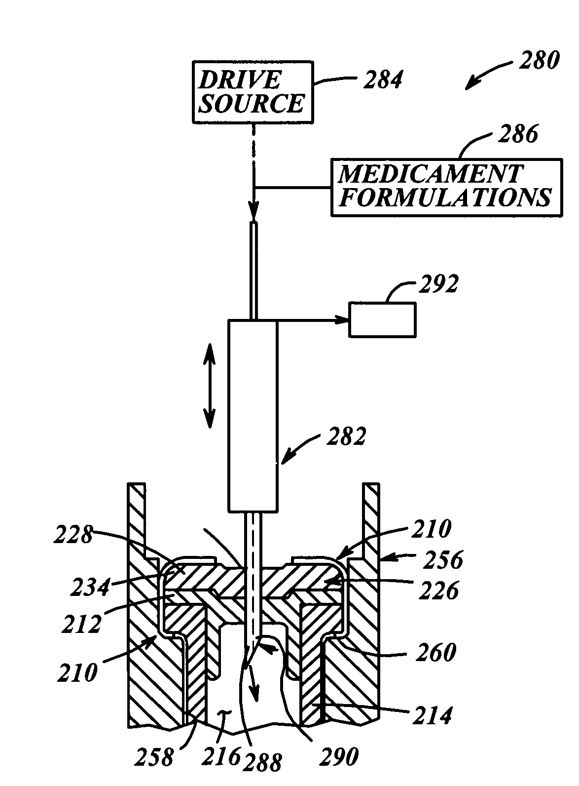
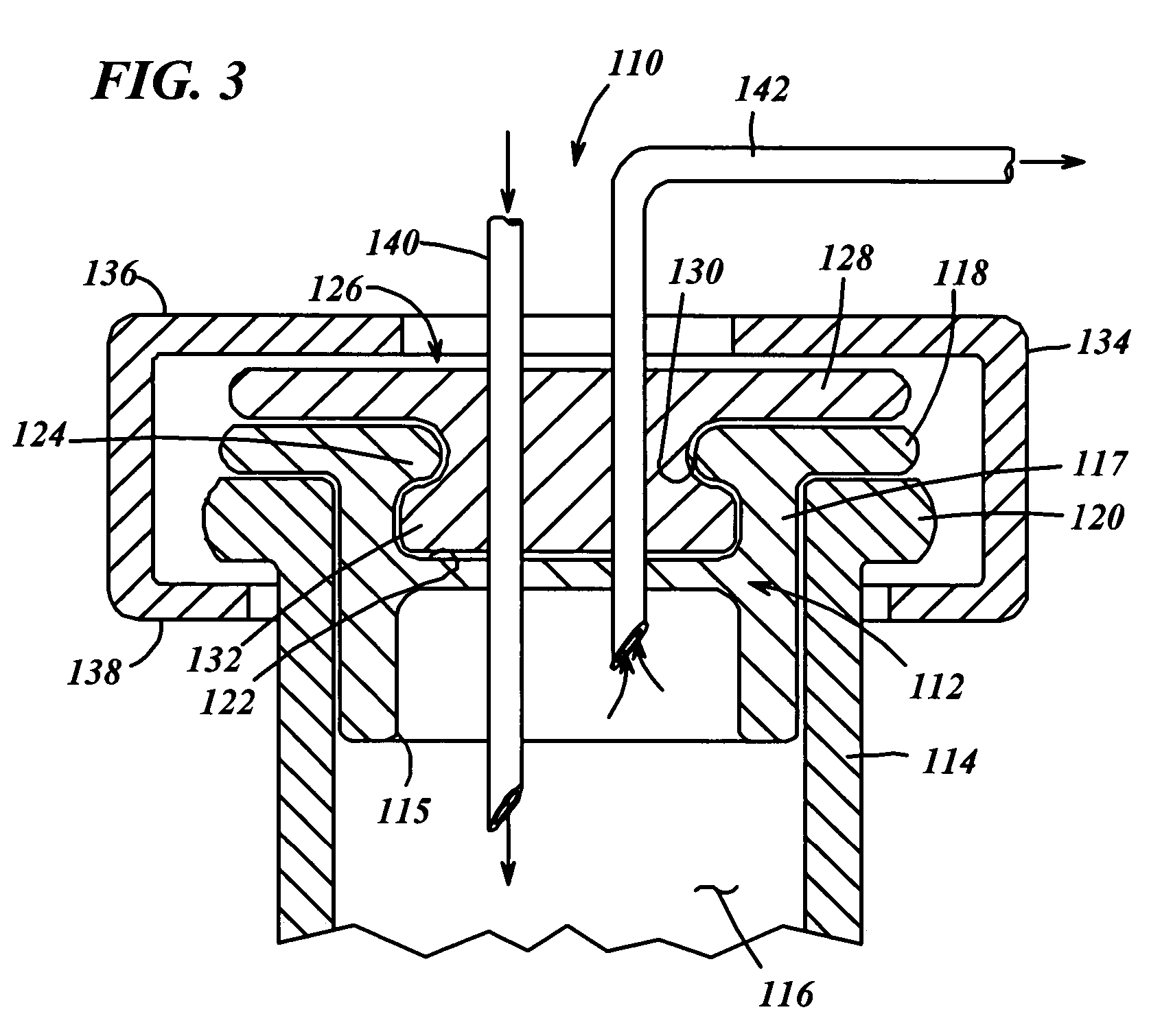
A resealable cap (110, 210) for a medicament vial (114, 214) has a base portion (112, 212) formed of vulcanized rubber or like material known for providing a stable environment for the medicament contained within the vial, and a resealable portion (126, 226) overlying the base portion. The resealable portion (126, 226) is made of low-density polyethylene or like material, and can be punctured by a needle or like injection member (140, 282) for dispensing medicament into the vial (114, 214). Prior to filling, the cap (110, 210) is assembled to the vial (114, 214) and the cap / vial assembly is sterilized. Then, a needle (140, 282) is inserted through the cap (110, 210) and medicament is introduced through the needle and into the vial. Upon withdrawal of the needle (140, 282), the penetrated region of the cap (248) is fused by laser (276) or direct heat sealing (264) to hermetically seal the needle hole (294) in the cap.

Description

CROSS-REFERENCE TO RELATED APPLICATIONS[0001]This patent application is a continuation-in-part of U.S. patent application Ser. No. 10 / 694,364, filed Oct. 27, 2003 now U.S. Pat. No. 6,805,170, entitled “Medicament Vial Having A Heat-Sealable Cap, And Apparatus and Method For Filling The Vial”, which is a continuation of similarly titled U.S. patent application Ser. No. 10 / 393,966, filed Mar. 21, 2003 now U.S. Pat. No. 6,684,916, which is a divisional of similarly titled U.S. patent application Ser. No. 09 / 781,846, filed Feb. 12, 2001, now U.S. Pat. No. 6,604,561, issued Aug. 12, 2003, which, in turn, claims the benefit of similarly titled U.S. Provisional Application Ser. No. 60 / 182,139, filed Feb. 11, 2000, and further, this application claims priority on similarly titled U.S. Provisional Patent Application No. 60 / 442,526, filed Jan. 28, 2003, and similarly titled U.S. Provisional Patent Application No. 60 / 484,204, filed Jun. 30, 2003. The foregoing applications and patent are hereb...

Claims


Application Information

Patent Timeline
IPC IPC(8): B65B1/20A61J1/14B65B1/04B65B3/00B65B57/02B65DB65D1/00B65D3/00B65D39/00B65D51/00
CPCB29C66/5344A61L2/08B29C65/16B29C65/18B29C66/001B29C66/342B29C66/534B29C67/004B65B3/003B65B7/161B65D51/002A61J1/18B29C65/1677B29C65/1654B29C65/00A61J1/1406A61J2001/1468A61M2207/00B29C65/1616B29L2031/7158B29L2031/753A61J1/1468B29C66/1222B29C66/1224B29C66/12461B29C66/1312B29C66/612B29C66/71B29C66/73755B29C66/7392B29C66/73921B29C66/7394B29C66/8322B29K2025/08
Inventor PY, DANIEL
Owner MEDINSTILL DEV
Learn More