Sealing member, rolling bearing, thin motor, and bearing device
a technology of sealing member and bearing, which is applied in the direction of bearing unit rigid support, instruments, and recording information storage, etc., can solve the problems of difficult engagement of sealing member with engaging groove, difficult installation of ring, and difficulty in ring engagement, so as to achieve easy peeling, reduce bonding force, and reduce the effect of bonding for
- Summary
- Abstract
- Description
- Claims
- Application Information
AI Technical Summary
Benefits of technology
Problems solved by technology
Method used
Image
Examples
first embodiment
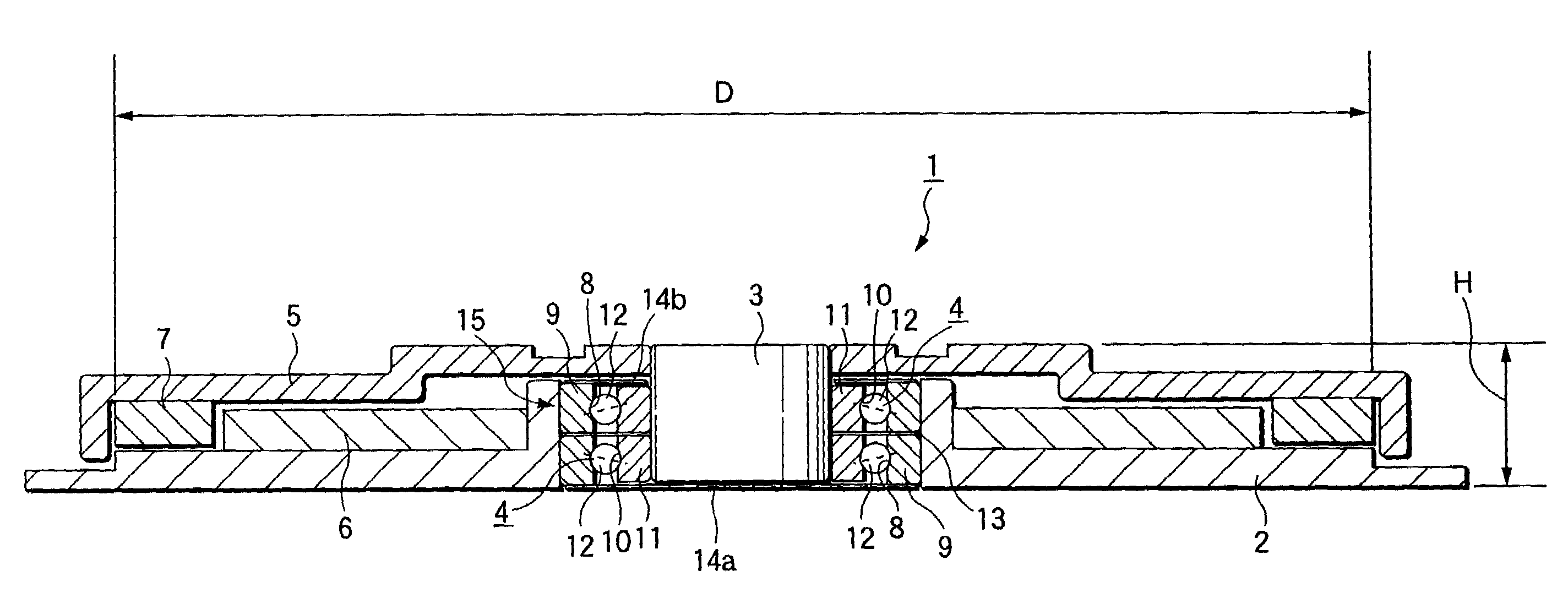
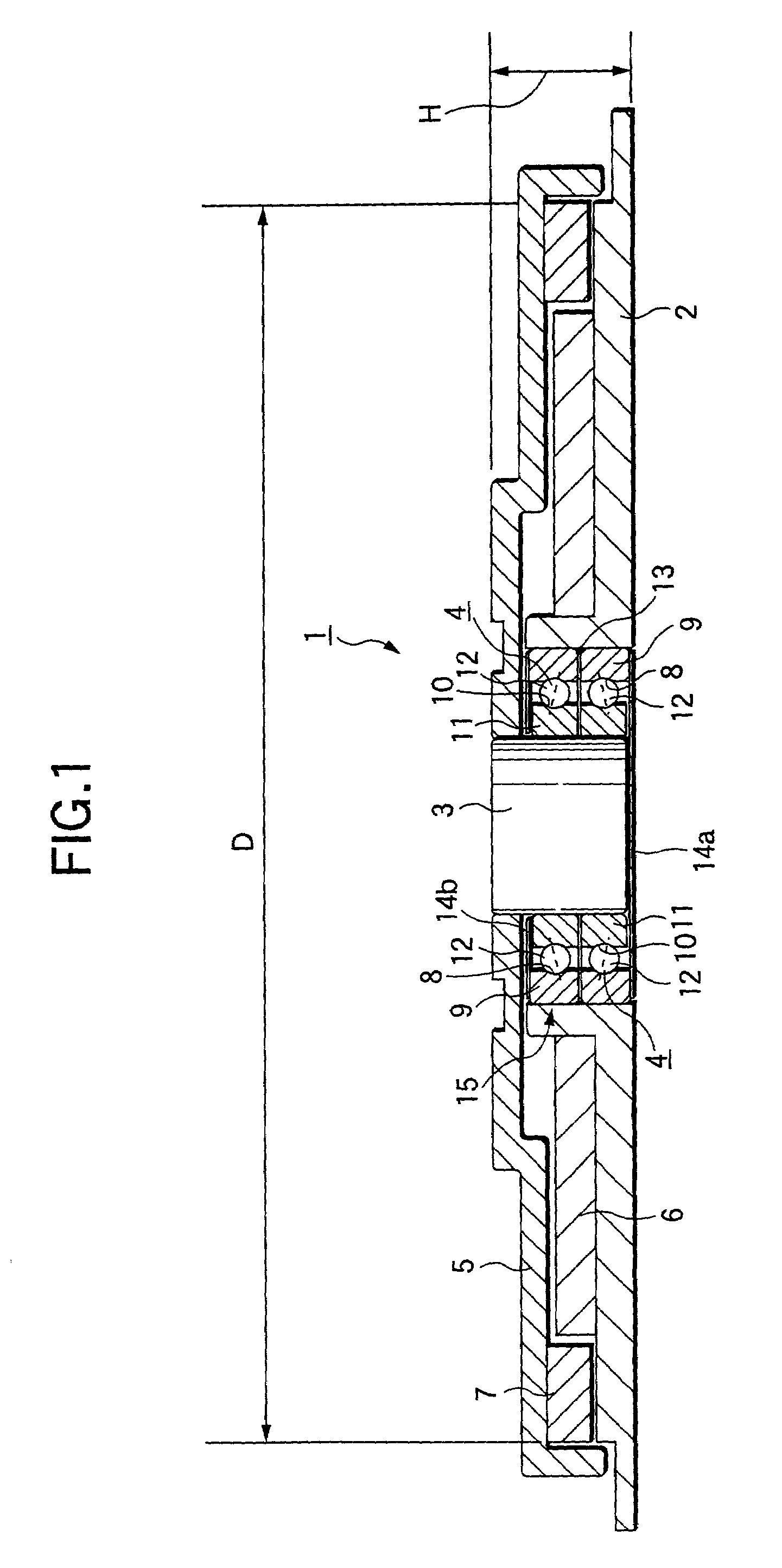
[0040]FIGS. 1 to 5 show the invention. A thin motor 1 of this embodiment has a rotation axis (second member) 3 supported rotatably by a pair of rolling bearings 4, 4 on the inner diameter side of a fixing member (housing=first member) 2 formed in a substantially round ring-like shape as a whole. Moreover, a rotating member (hub=second member) 5 formed in a substantially round ring-like shape as a whole is fitted externally and fixed with the part of one end part (upper end part in FIGS. 1 to 2) of the rotation axis 3, projecting from the upper (The up and down direction here denotes the direction in the figures, and thus the practical use state is not limited thereby. The same is applied throughout the entirety of the specification.) rolling bearing 4. The outer circumferential surface of a stator 6 fixed on the upper surface inner diameter side part of the fixing member 2 and the inner circumferential surface of a rotor 7 fixed on the lower surface outer diameter side part of the r...
third embodiment
[0046]Moreover, in the case of this embodiment, the outer rings 9, 9 constituting the double row rolling bearing 15 can be formed integrally as in the third embodiment described later (see FIG. 7).
[0047]In the case of assembling the thin motor 1 with the above-mentioned configuration to an HDD, an IC cooling fan, or the like, the fixing member 2 is fixed on a fixing part of a housing, or the like as well as a member to be rotated such as a hard disc, a fan, or the like is supported or fixed on the rotating member 5 directly or via another member.
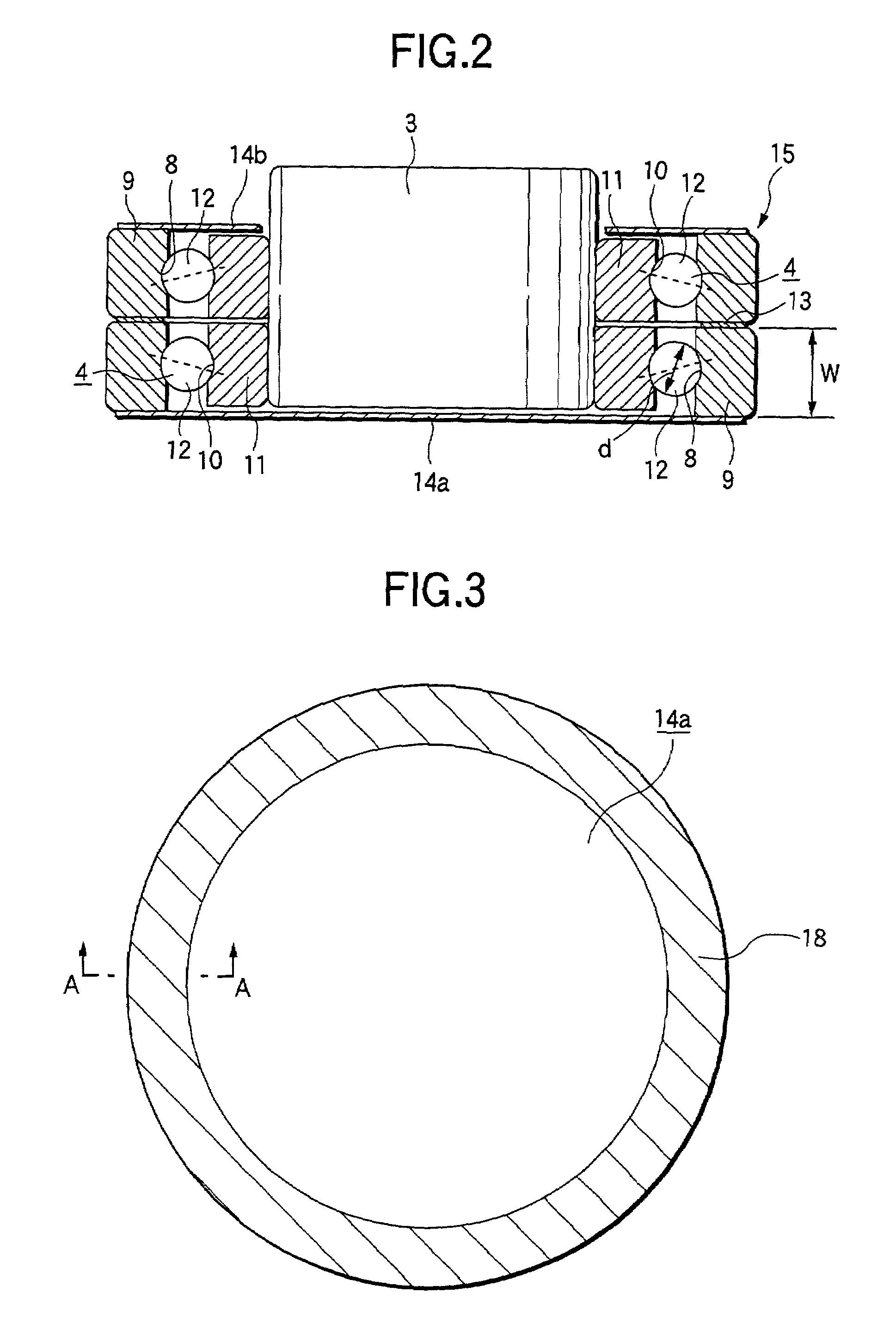
[0048]In the case of the sealing members 14a, 14b, the bearings 4, 4 and the thin motor 1 of this embodiment with the above-mentioned configuration, at the time of assembling the sealing members 14a, 14b with the rolling bearings 4, 4, one side surface outer circumferential rim part of each of the sealing members 14a, 14b is bonded and fixed on the outer end surface of each of the outer rings 9, 9. Therefore, even in the case the axial direc...
fourth embodiment
[0056]FIGS. 9A and 9B are a cross-sectional view showing a rolling bearing and a bearing device according to the invention.
[0057]The rolling bearing of this embodiment is a double row ball bearing 101. The double row ball bearing 101 comprises two inner rings 104, 105 and two outer rings 106, 107, with the entire inner circumferential surface of the first inner ring 104 covered with the second inner ring 105. The width of the second inner ring 105 is 1.2 mm, and the width of the inner circumferential part 142 of the first inner ring 104 is about ⅓ thereof.
[0058]Balls 131, 132 of the double row ball bearing 101 are disposed offset with each other in the bearing radial direction. The ball 131 in one row (first row) is provided on the outer side with respect to the ball 132 in the other row (second row) with respect to the bearing radial direction. The diameter difference of the ball 131 pitch circle and the ball 132 pitch circle is about 104 times as much as the diameter of the balls ...
PUM
 Abstract
Description
Claims
Application Information
 - R&D
- Intellectual Property
- Life Sciences
- Materials
- Tech Scout
- Unparalleled Data Quality
- Higher Quality Content
- 60% Fewer Hallucinations
Browse by: Latest US Patents, China's latest patents, Technical Efficacy Thesaurus, Application Domain, Technology Topic, Popular Technical Reports.
© 2025 PatSnap. All rights reserved.Legal|Privacy policy|Modern Slavery Act Transparency Statement|Sitemap|About US| Contact US: help@patsnap.com


