Polymer electrolyte fuel cell stack and method for operating the same and gas vent valve
- Summary
- Abstract
- Description
- Claims
- Application Information
AI Technical Summary
Benefits of technology
Problems solved by technology
Method used
Image
Examples
first embodiment
[0084][First Embodiment]
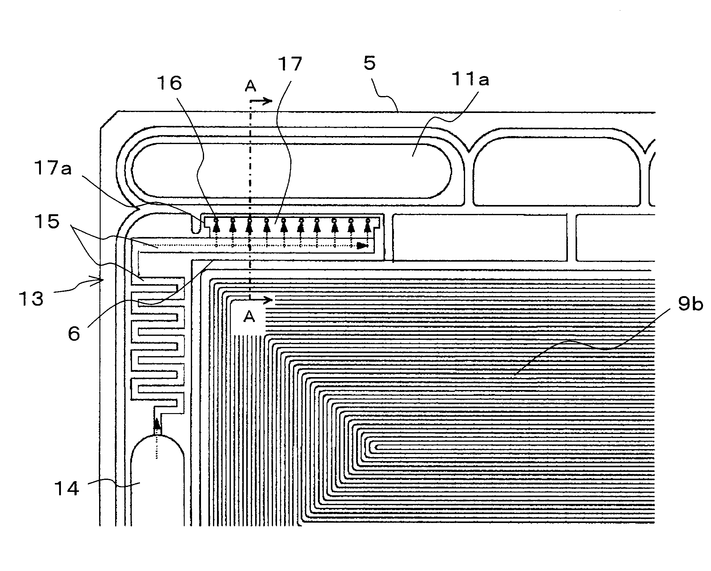
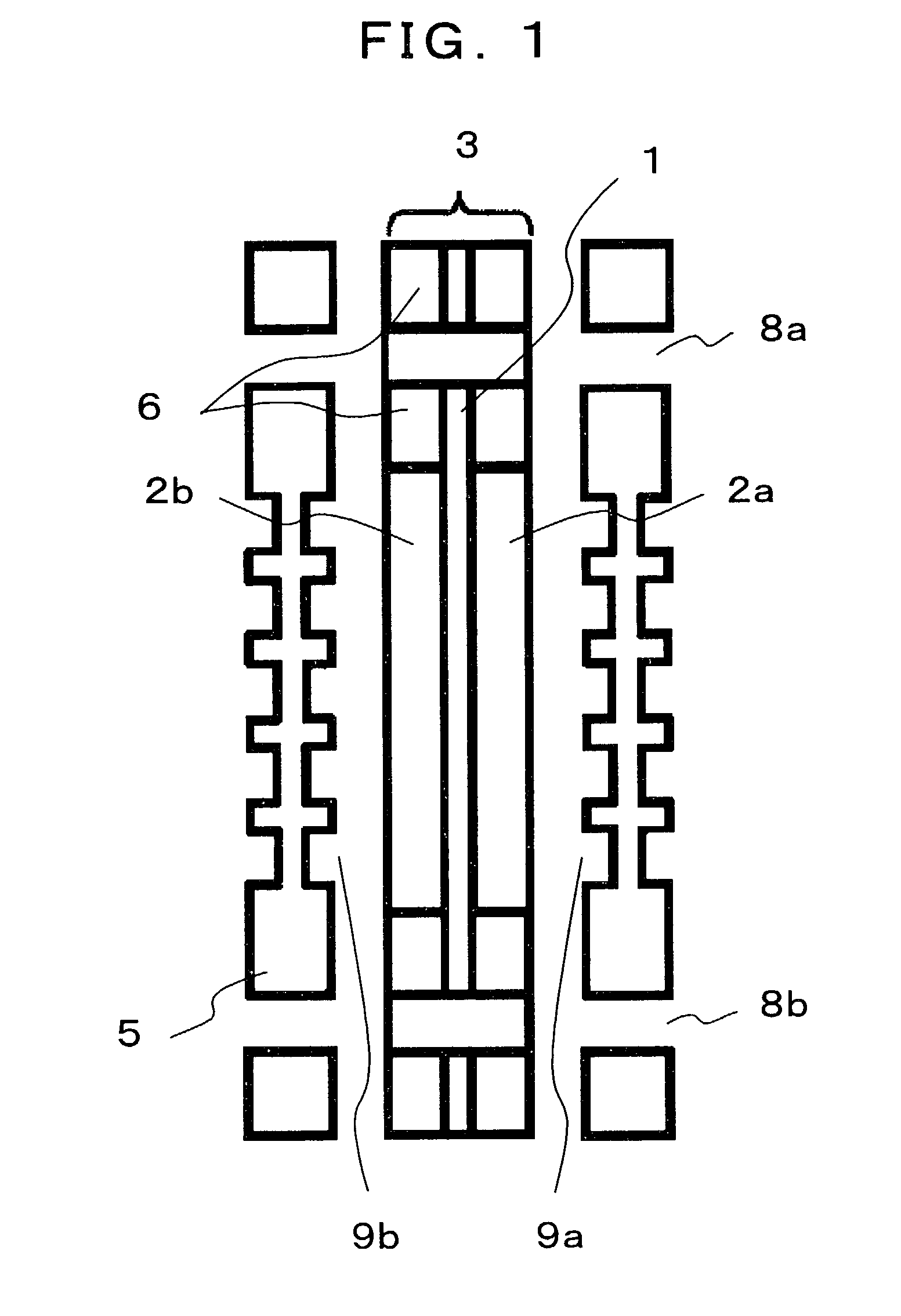
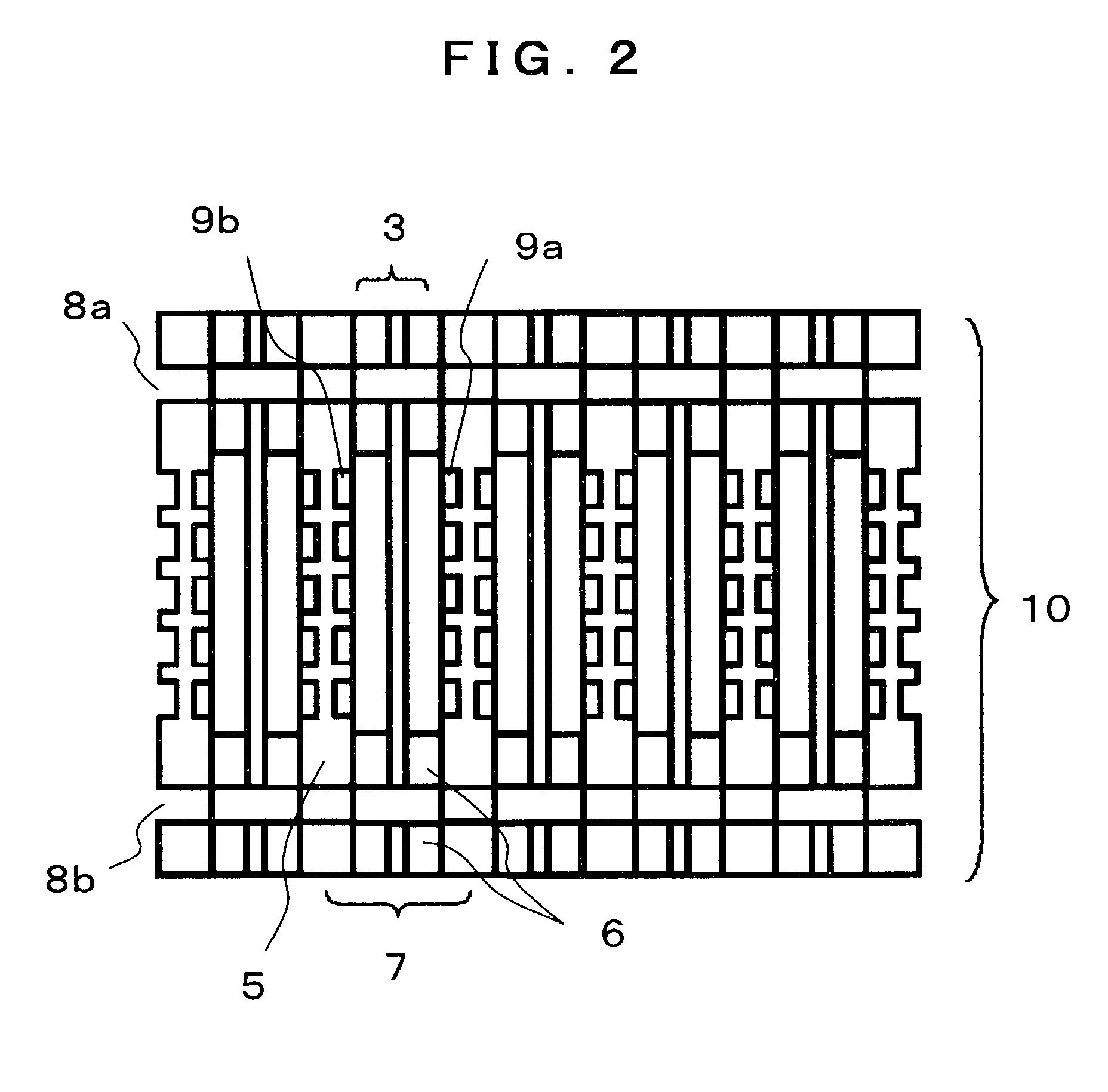
[0085]FIG. 3 shows the oxidant gas supply surface of a reactant gas supply separator 5 according to a first embodiment of the present invention. The reactant gas supply separator 5 is formed by molding carbon material in a plate. Oxidant gas supply grooves 9b are formed for oxidant gas passing there through in the central part of the reactant gas supply separator 5. The reactant gas supply separator 5 is erected vertically when electric power is generated by the fuel cell stack 10.
[0086]There are a fuel gas supply manifold 11a and an oxidant gas supply manifold 12a in the upper marginal portion of the reactant gas supply separator 5, and there is a fuel gas exhaust manifold 11a and an oxidant gas exhaust manifold 12b in the lower marginal portion of the reactant gas supply separator 5. In addition, there is a water supply manifold 14 in the left hand marginal portion of the reactant gas supply separator 5, as shown in FIG. 3.
[0087]The oxidant gas supplied to ...
second embodiment
[0107][Second Embodiment]
[0108]The second embodiment of the invention is a polymer electrolyte fuel cell stack similar to the first embodiment described above, and is characterized in that non-woven fabric of hydrophilic carbon material is used for the porous body 20 disposed in the buffer section 17.
[0109]According to the second embodiment described above, water is supplied uniformly to the fuel gas supply grooves 9a, and the solid high polymer fuel stack 10 can be stably operated from the time immediately after the start of the operation. In comparison to this embodiment, a fuel cell stack 10 using less hydrophilic carbon material as porous bodies 20 would require additional operation such temporary increase of water flow rate supplied to the fuel cell stack 10, and even after such operation, fuel cell performance may fluctuate due to non-uniform water flow distribution. This may be because of gas bubbles remained in the porous bodies 20 obstructing equal water distribution.
[0110]...
third embodiment
[0112][Third Embodiment]
[0113]The third embodiment of the invention is a polymer electrolyte fuel cell stack similar to the first embodiment described above, but the water supply means 13 is formed as shown in FIG. 9. FIG. 9 is a cross-sectional view of the water supply means 13 of the third embodiment. The third embodiment is characterized in lids 23 of water non-permeability covering the water supply grooves 15 and the buffer sections 17.
[0114]The lids 23 of water non-permeability may be sheets of polyethylene sulphonic resin of 250 micrometers in thickness, for example. The oxidizer electrode substrates 19b which are electrode bodies of the membrane electrode assemblies 3 are isolated by the gaskets 6, and the solid high polymer members 1 of the membrane electrode assemblies 3 are extended to cover the sheet of polyethylene sulphonic resin. The supplied water flows in the water supply grooves 15, and to the buffer sections 17 as shown by dotted arrows in FIG. 9. Then, the water f...
PUM
 Abstract
Description
Claims
Application Information
 - R&D
- Intellectual Property
- Life Sciences
- Materials
- Tech Scout
- Unparalleled Data Quality
- Higher Quality Content
- 60% Fewer Hallucinations
Browse by: Latest US Patents, China's latest patents, Technical Efficacy Thesaurus, Application Domain, Technology Topic, Popular Technical Reports.
© 2025 PatSnap. All rights reserved.Legal|Privacy policy|Modern Slavery Act Transparency Statement|Sitemap|About US| Contact US: help@patsnap.com


