
Tapered multi-layer thermal actuator and method of operating same

a thermal actuator and multi-layer technology, applied in the direction of piezoelectric/electrostrictive/magnetostrictive devices, coatings, printing, etc., can solve the problems of unreliable use of such devices as liquid drop emitters and microvalves, severe limits on the formulation of inks and other liquids, and low cost of micro-electromechanical devices. achieve the effect of reducing input energy

Inactive Publication Date: 2006-04-18
EASTMAN KODAK CO
View PDF24 Cites 4 Cited by
  • Summary
  • Abstract
  • Description
  • Claims
  • Application Information

AI Technical Summary

Benefits of technology

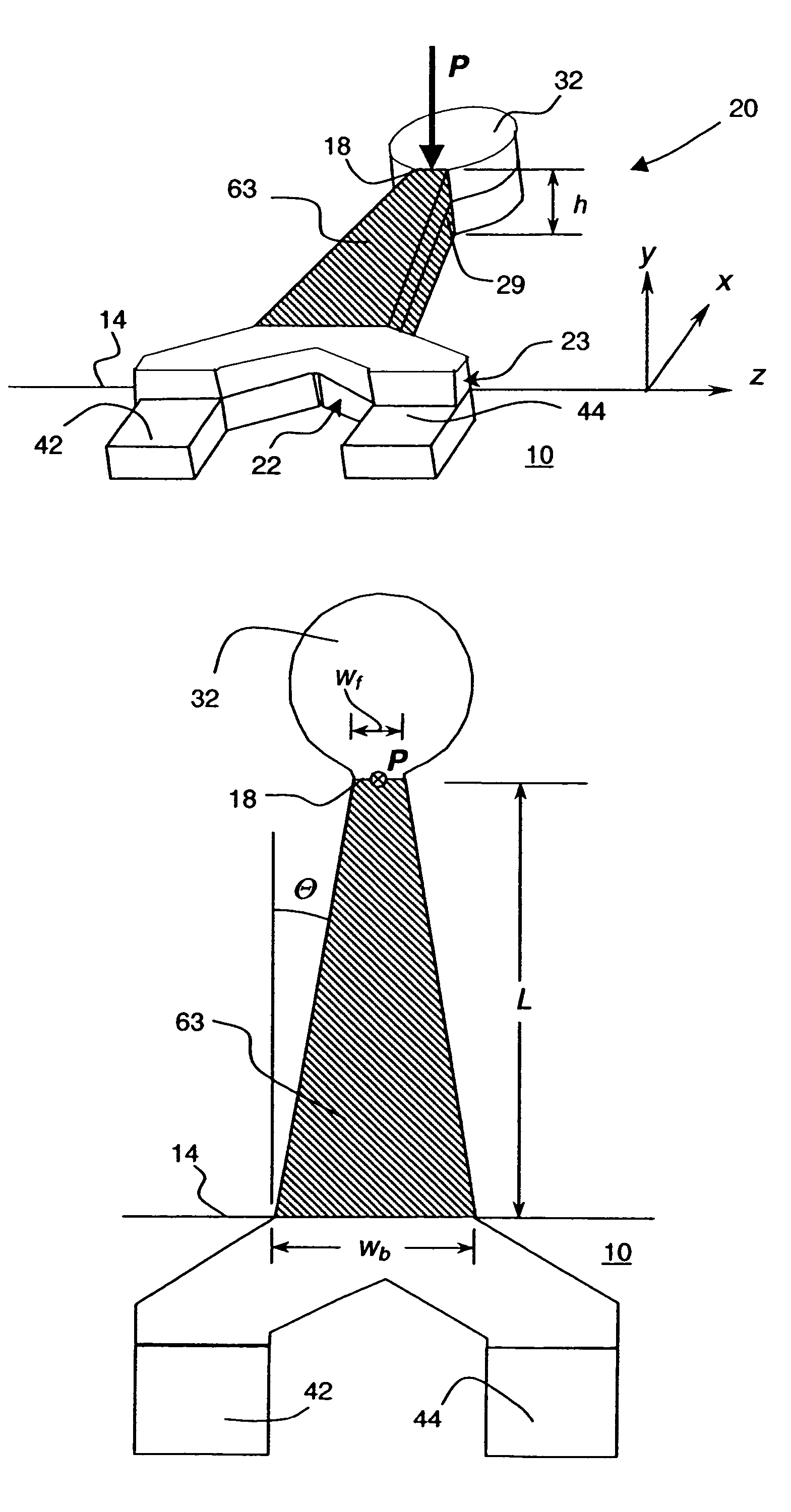
[0020]It is therefore an object of the present invention to provide a thermo-mechanical actuator which uses reduced input energy and which does not require excessive peak temperatures.
[0021]It is also an object of the present invention to provide an energy efficient thermal actuator which comprises dual actuation means that move the thermal actuator in substantially opposite directions allowing rapid restoration of the actuator to a nominal position and more rapid repetitions.
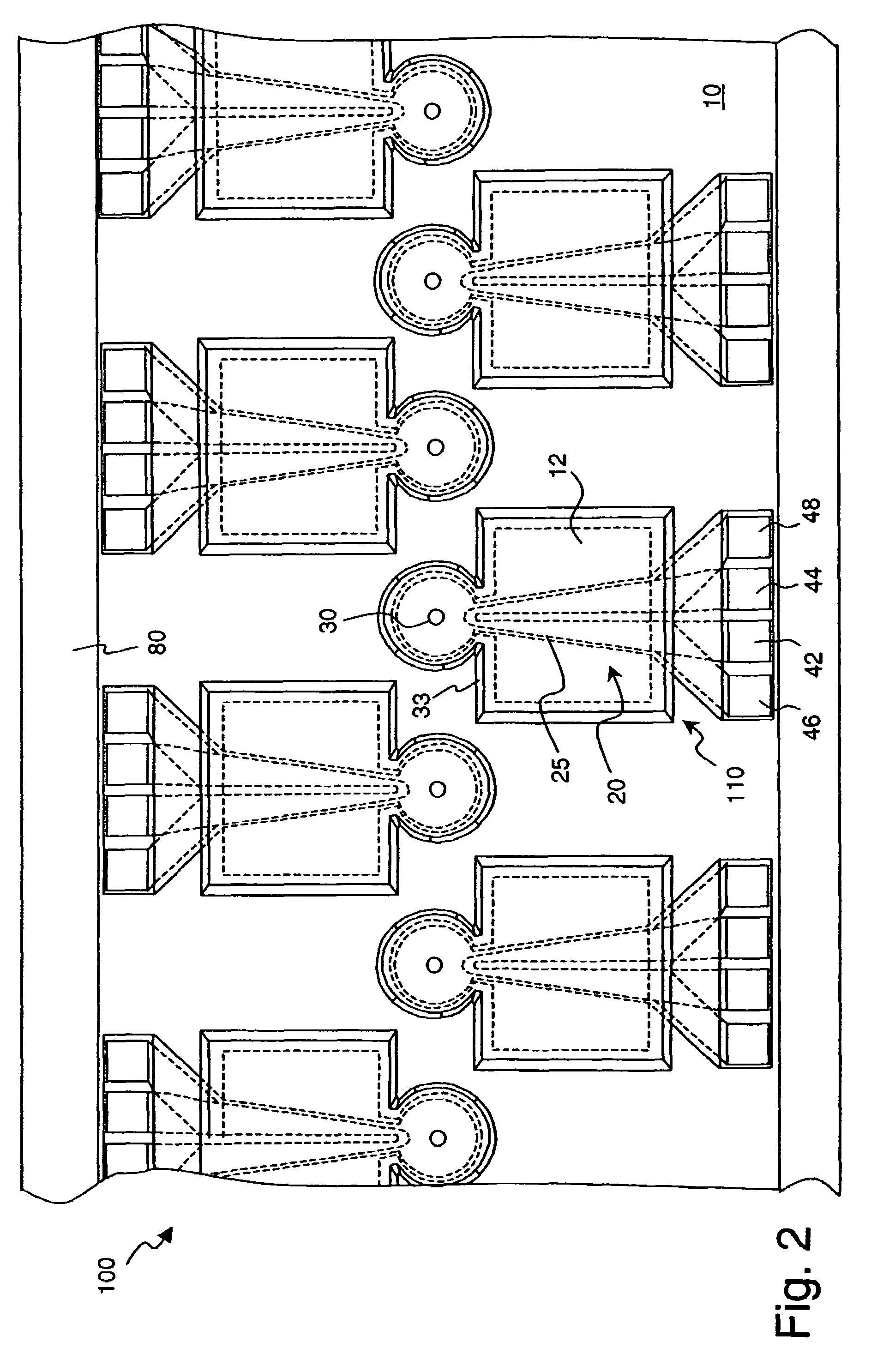
[0023]It is further an object of the present invention to provide a liquid drop emitter which is actuated using a thermo-mechanical bender portion which is shaped to reduce the affect of loading or back pressures and energized by a heater resistor having a spatial thermal pattern to improve energy efficiency.

Problems solved by technology

Micro-electromechanical devices are potentially low cost, due to use of microelectronic fabrication techniques.
This temperature exposure places severe limits on the formulation of inks and other liquids that may be reliably emitted by thermal ink jet devices.
The beam is heated by a resistor causing it to bend due to a mismatch in thermal expansion of the layers.
However, the thermo-mechanical bending portions of the disclosed thermal actuators are not configured to be operated in contact with a liquid, rendering them unreliable for use in such devices as liquid drop emitters and microvalves.
The disclosed designs are based on coupled arm structures which are inherently difficult to fabricate, may develop post-fabrication twisted shapes, and are subject to easy mechanical damage.
The thermal actuator designs disclosed in Silverbrook '113 have structurally weak base ends which are subjected to peak temperatures, possibly causing early failure.
Further, the thermal actuator designs disclosed in Silverbrook '453 are directed at solving an anticipated problem of an excessive temperature increase in the center of the thermal actuator, and do not offer increased energy efficiency during actuation.
The disclosed actuator designs have heat sink components which increase undesirable liquid backpressure effects when used immersed in a liquid, and, further, add isolated mass which may slow actuator cool down, limiting maximum reliable operating frequencies.

Method used


Image

  • Tapered multi-layer thermal actuator and method of operating same
  • Tapered multi-layer thermal actuator and method of operating same
  • Tapered multi-layer thermal actuator and method of operating same

Examples


Embodiment Construction

[0069]The invention has been described in detail with particular reference to certain preferred embodiments thereof, but it will be understood that variations and modifications can be effected within the spirit and scope of the invention.

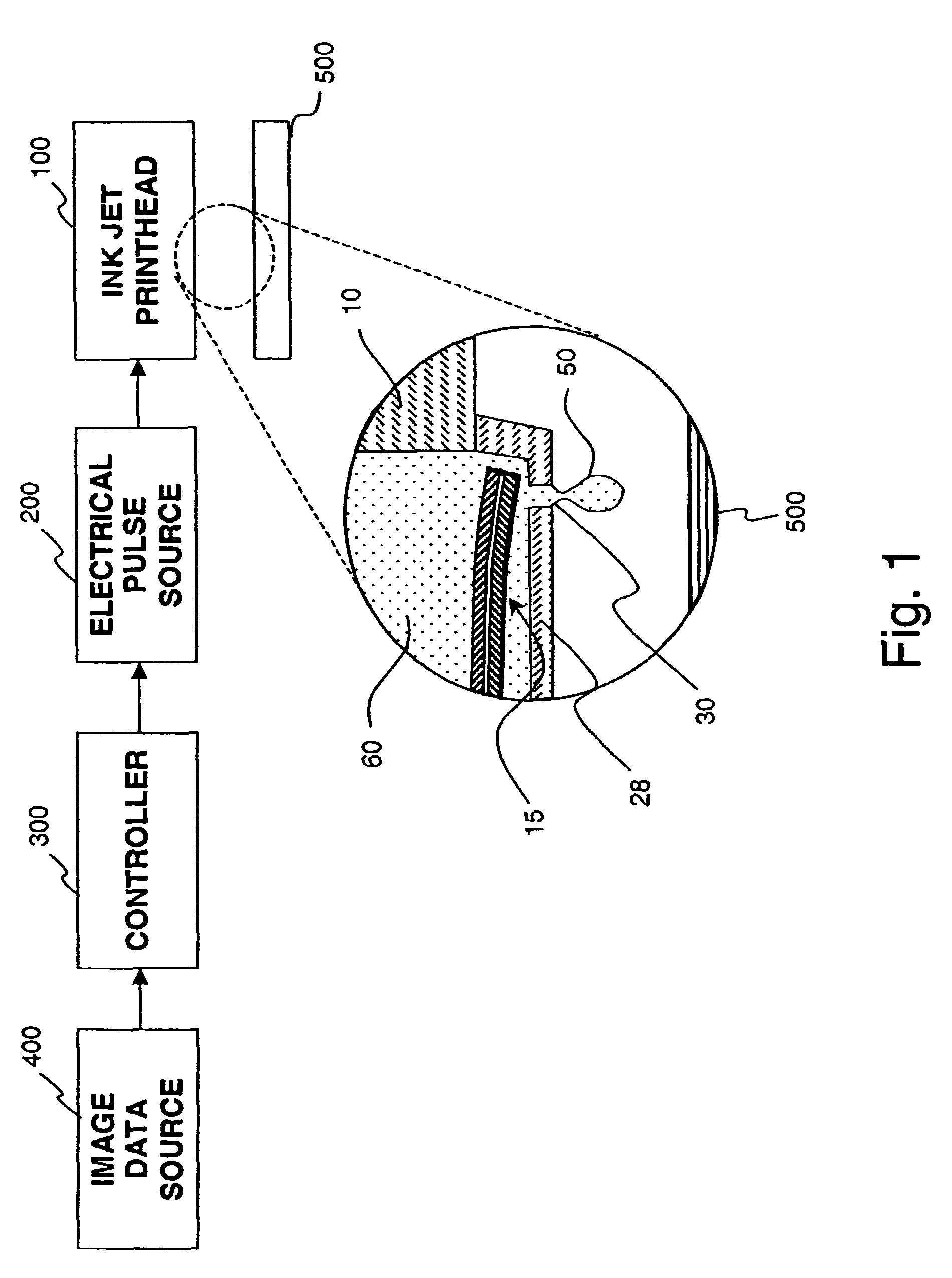
[0070]As described in detail herein below, the present invention provides apparatus for a thermo-mechanical actuator and a drop-on-demand liquid emission device and methods of operating same. The most familiar of such devices are used as printheads in ink jet printing systems. Many other applications are emerging which make use of devices similar to ink jet printheads, however which emit liquids other than inks that need to be finely metered and deposited with high spatial precision. The terms ink jet and liquid drop emitter will be used herein interchangeably. The inventions described below provide apparatus and methods for operating drop emitters based on thermal actuators so as to improve overall drop emission productivity.

[0071]Turning first to ...


PUM


Abstract

An apparatus for and method of operating a thermal actuator for a micromechanical device, especially a liquid drop emitter for use in an ink jet printhead, is disclosed. The disclosed thermal actuator includes a base element and a cantilevered element including a thermo-mechanical bender portion extending from the base element to a free end tip. The thermo-mechanical bender portion includes a barrier layer constructed of a dielectric material having low thermal conductivity, a first deflector layer constructed of a first electrically resistive material having a large coefficient of thermal expansion, and a second deflector layer constructed of a second electrically resistive material having a large coefficient of thermal expansion wherein the baffler layer is bonded between the first and second deflector layers.

Description

[0001]This application is a divisional of prior application Ser. No. 10 / 293,982, filed Nov. 13, 2002 now U.S. Pat. No. 6,817,702.CROSS REFERENCE TO RELATED APPLICATION[0002]Reference is made to commonly-assigned co-pending U.S. patent applications: U.S. Ser. No. 10 / 293,653 filed Nov. 13, 2002, now U.S. Pat. No. 6,721,020, entitled “Thermal Actuator With Spatial Thermal Pattern,” of Delametter, et al.; U.S. Ser. No. 10 / 293,077 filed Nov. 13, 2002, now U.S. Pat. No. 6,820,964, entitled “Tapered Thermal Actuator,” of Trauemicht, et al.; U.S. Ser. No. 10 / 227,079, filed Nov. 13, 2002, now U.S. Pat. No. 6,824,249 entitled “Tapered Thermal Actuator,” of Delametter et al.; U.S. Ser. No. 10 / 154,634, filed May 23, 2002, now U.S. Pat. No. 6,598,960 entitled “Multi-layer Thermal Actuator with Optimized Heater Length and Method of Operating Same,” of Cabal et al.; U.S. Ser. No. 10 / 071,120, filed Feb. 08, 2002, now U.S. Pat. No. 6,588,884 entitled “Tri-layer Thermal Actuator and Method of Operati...

Claims


Application Information

Patent Timeline
Patent Type & Authority Patents(United States)
IPC IPC(8): B41J2/05B41J2/04B41J2/045B05C5/00B41J2/055B41J2/14B41J2/16B81B3/00
CPCB41J2/14427B41J2/1648B41J2/1631B41J2/1628
Inventor DELAMETTER, CHRISTOPHER N.FURLANI, EDWARD P.LEBENS, JOHN A.TRAUERNICHT, DAVID P.CABAL, ANTONIOROSS, DAVID S.POND, STEPHEN F.
Owner EASTMAN KODAK CO
Learn More