
Self-maintenance rolling bearing and assembling method thereof

A rolling bearing, bearing technology, applied in the direction of roller bearings, bearing components, shafts and bearings, etc., can solve problems such as increased design costs

Inactive Publication Date: 2013-12-04
AB SKF
View PDF3 Cites 4 Cited by
  • Summary
  • Abstract
  • Description
  • Claims
  • Application Information

AI Technical Summary

Problems solved by technology

Cannot be done without right angle circlips as there is no rib on the outer ring side to fit the bearing
[0005] The use of additional components increases the design expense and limits the flexibility in selecting available rolling bearings, for example when standardized components must be used for financial reasons, such as right-angle circlips, O-rings or serrations commonly available on the market lock up

Method used


Image

  • Self-maintenance rolling bearing and assembling method thereof
  • Self-maintenance rolling bearing and assembling method thereof
  • Self-maintenance rolling bearing and assembling method thereof

Examples


Embodiment Construction

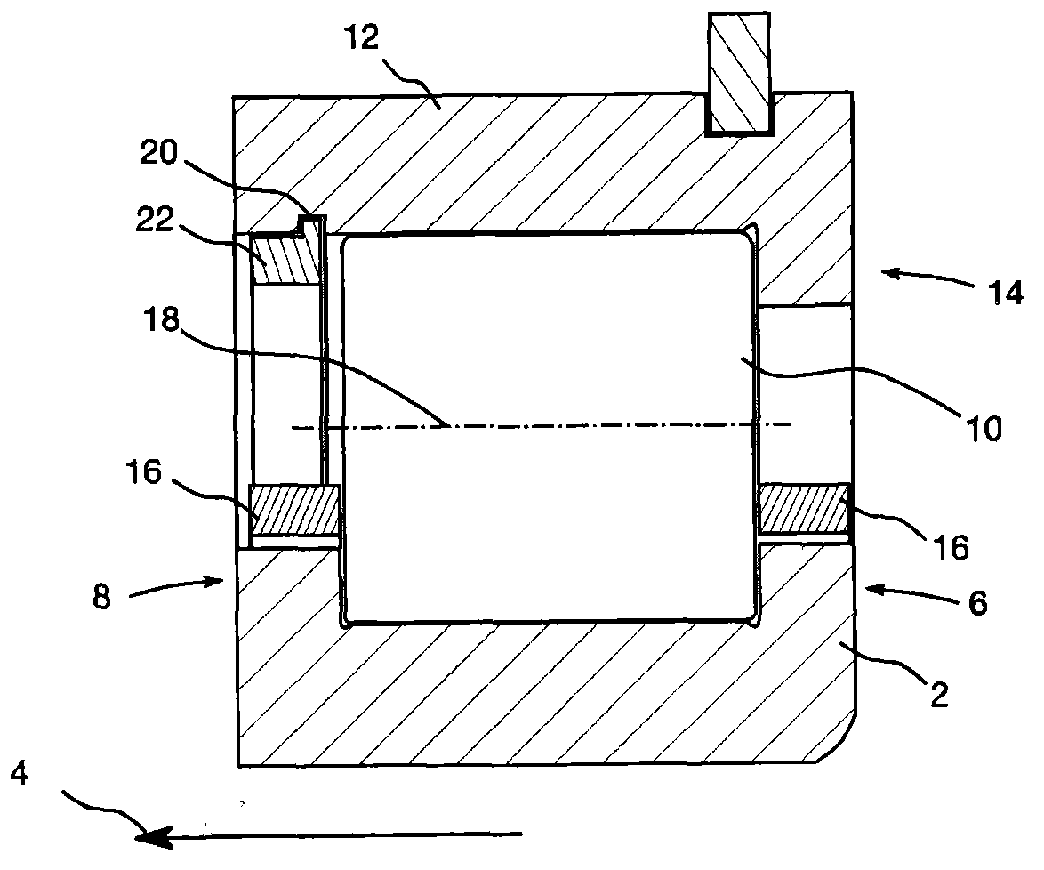
[0021] attached figure 1 Shown is a cross-sectional view of a conventional cylindrical roller bearing that utilizes a right-angle circlip to prevent disassembly. in the attached figure 1 In the case shown, the bearing inner ring 2 has not only a first rib 6 at the first end of its raceway, but also a second rib 8 at the opposite end of its raceway in the axial direction 4 . Rolling bodies or cylindrical rollers 10 are arranged within ribs 6 and 8 . The bearing outer ring 12 has a rib 14 only on the first axial end of its raceway, and no rib on the opposite end of the raceway, so that the bearing can be mounted or assembled. in the attached figure 1 In the example shown, the bearing cage 16 is guided below the pitch circle. Here, the ideal circle formed by the center of the cylindrical roller when the bearing rolls can be used as the pitch circle. The ideal radius of the pitch circle can thus be derived from the distance between the axis of symmetry 18 of the cylindrical r...


PUM


Abstract

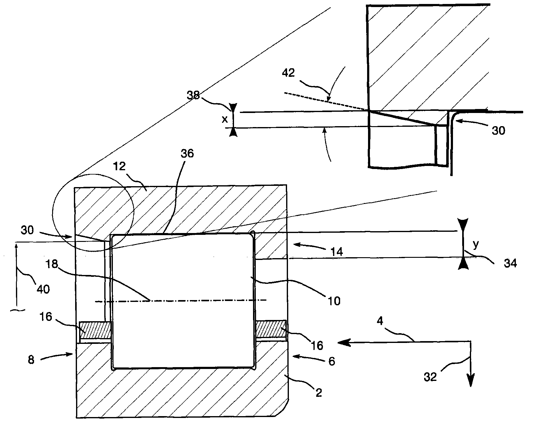
The invention relates to a self-maintenance rolling bearing. The self-maintenance rolling bearing comprises a roller ring and a first bearing sleeve ring (2) with two ribs (6, 8) which extend along a radial direction (32) to first rib height (34). The self-maintenance rolling bearing also comprises a second bearing sleeve ring. A first rib which extends along the radial direction to the first rib height is arranged at a first axial end of a roller path of the second bearing sleeve ring, and a second rib which extends along the radial direction to second rib height is arranged at a second axial end of the roller path of the second bearing sleeve ring. The second rib height is less than the first rib height. In assembling, the second bearing sleeve ring or the roller ring is heated to an assembling temperature form an environment temperature. At the assembling temperature, the second rib of the second bearing sleeve ring can move relatively to the roller ring along the axial direction because of second bearing sleeve ring or roller ring diameter variation caused by the temperature.

Description

technical field [0001] The invention relates to how to efficiently assemble, damage-free transport and install rolling bearings, especially cylindrical roller bearings or tapered roller bearings. Background technique [0002] In some types of rolling bearings, structural measures need to be taken to prevent the rolling bearing from disintegrating during transportation or installation, causing the bearing to be damaged or even lose its function. Taking cylindrical roller bearings or tapered roller bearings as an example, the bearing ring cannot be designed as a two-component type, because if the two-component type design is adopted, the load must be carried at the junction, so it is necessary to design at least one side without Rib bearing inner ring or bearing outer ring. This enables the bearing inner ring or the bearing outer ring to be assembled with the rolling elements or separately separated from the other bearing ring. [0003] However, there is a risk that the bear...

Claims


Application Information

Patent Timeline
IPC IPC(8): F16C19/22F16C33/58F16C43/04
Inventor R·哈斯B·埃克
Owner AB SKF
Learn More