Deployable truss beam with orthogonally-hinged folding diagonals

a technology of orthogonal bending and truss beams, applied in the field of deployable truss beams, can solve the problems of high cost, high complexity, high cost, etc., and achieve the effect of greater stability

Inactive Publication Date: 2006-04-18
CPI TECH
View PDF53 Cites 41 Cited by
  • Summary
  • Abstract
  • Description
  • Claims
  • Application Information

AI Technical Summary

Benefits of technology

[0006]In the basic form, the invention can be used as a beam or a mast in a wide variety of applications. As a beam, it can be supported or mounted at each end, or cantilever mounted. As a mast, it is base-mounted with guy cables as required. End bearing pads may be affixed to the ends of the chordal members and end struts to provide additional stability and strength when the truss is deployed.
[0008]Another alternative embodiment of the invention is a dual rectangular configuration, where two single section trusses are connected along two secondary chords, providing greater strength and stability. Advantages include the ability to withstand transverse load reversal and, as a mast, no requirement for guy cables. In a variation on this embodiment, the side diagonals are removed from the long side of the dual rectangular configuration to reduce cost and weight.
[0011]Thus, the invention in its various embodiments possesses several favorable characteristics relative to those trusses cited above, including, but not limited to, (i) use of the new orthogonal hinge folding method to achieve synchronous, coordinated motion of all members during extension or retraction, (ii) greater stability, (iii) self formation, so that no dedicated auxiliary mechanisms or structures are required other than simple means to offset gravity and friction, if required, (iv) deployment along the truss longitudinal axis with a length extension ratio that can be, but does not have to be, more than 15 times the retracted length, (v) minimization of cost, weight, and complexity by the elimination of unnecessary truss members and use of alternative forms of truss chordal members, and (vi) adaptability to actuation methods that can vary from fully manual to fully automatic, depending on the application requirements. Applications for the invention include, but are not limited to, scaffolding, platforms and construction equipment, crane and equipment booms, towers and masts, vehicle frames, theater stage roofs and lighting equipment, stowable equipment mounts, shelters, space structures and space vehicle booms, and exhibition display frames.

Problems solved by technology

Undesirable features of existing deployable trusses include complexity, inability to move in a coordinated and synchronous manner, requirements for a dedicated deployer and auxiliary mechanisms, and high cost.
Thus, what is needed is a deployable truss that achieves synchronous coordinated motion of all members while extending or retracting, is stable and self-forming and requires no dedicated auxiliary mechanisms and structures, and yet remains low in weight, complexity, and cost.

Method used


Image

  • Deployable truss beam with orthogonally-hinged folding diagonals
  • Deployable truss beam with orthogonally-hinged folding diagonals
  • Deployable truss beam with orthogonally-hinged folding diagonals

Examples


Embodiment Construction

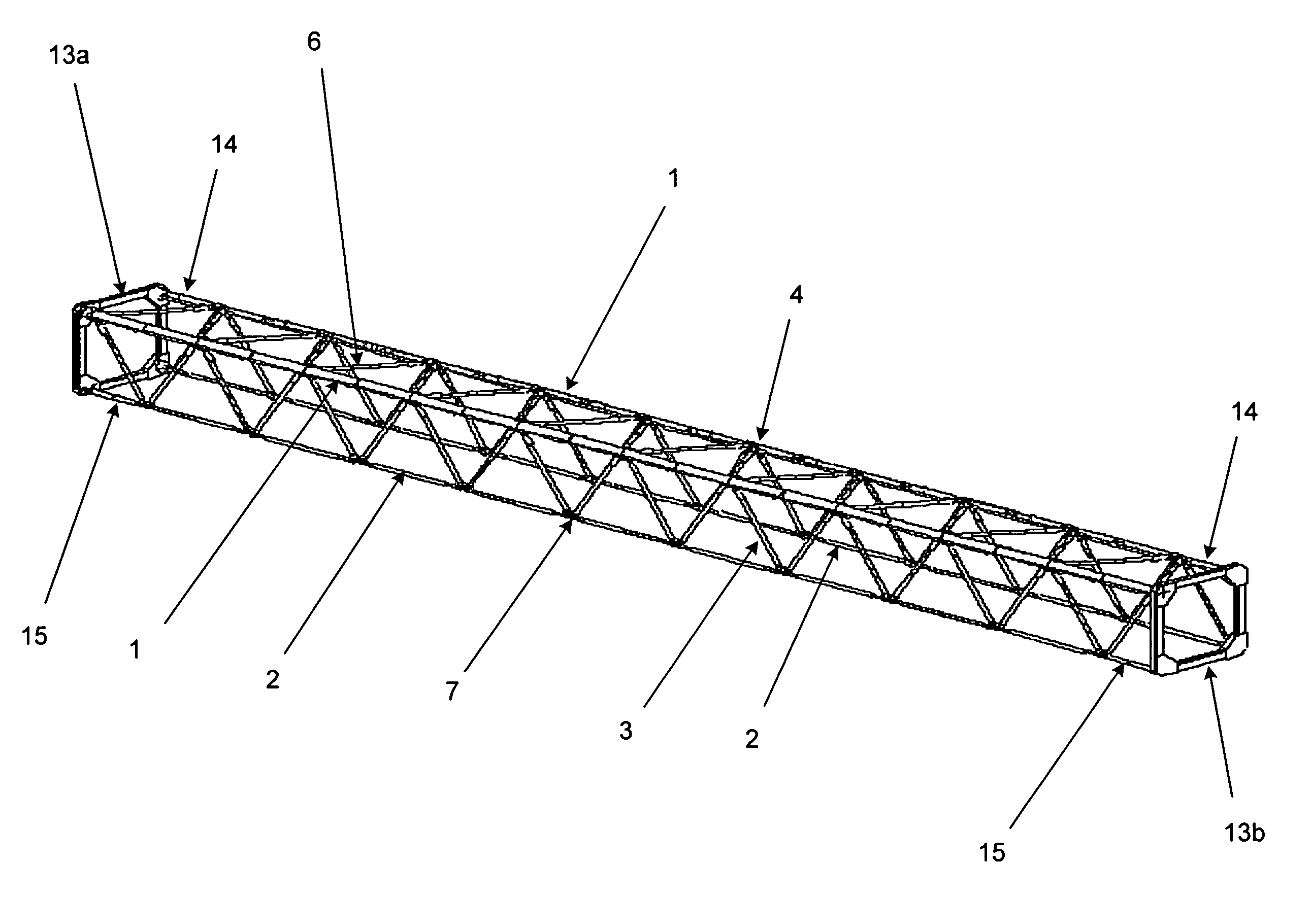
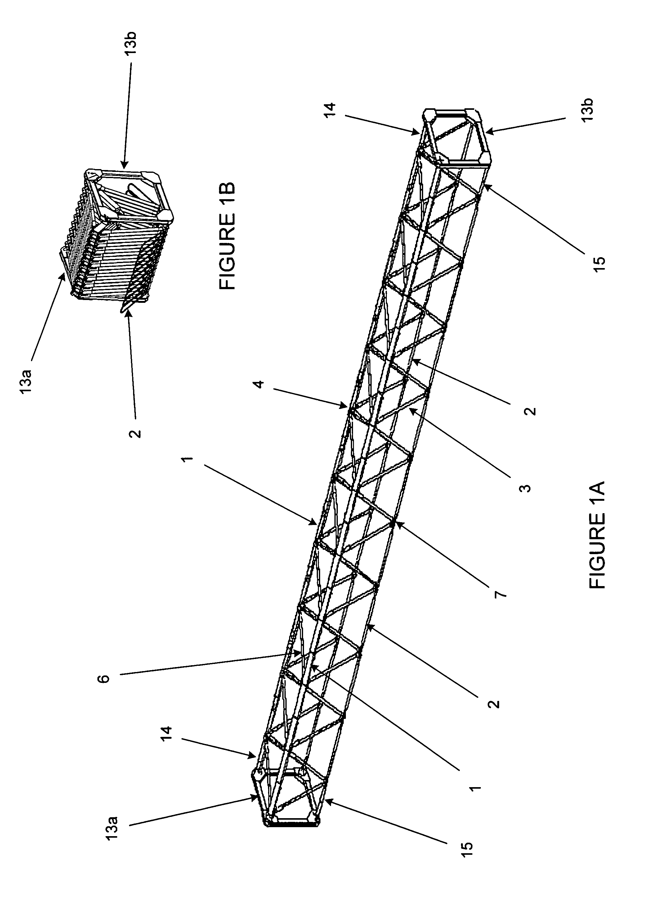
[0018]FIGS. 1A and 1B show the general configuration of a deployable single-section truss beam in the in the retracted and extended (deployed) states. Four longitudinal truss chords are formed by primary 1, and secondary 2 chordal members. As depicted in FIGS. 1A and 1B, the primary chordal members 1 are compression structures and the secondary chordal members 2 are tension structures, although the chordal members are not limited to this configuration. Compression chordal members may be rigid or hinged 1, while tension chordal members may be flexible, hinged or cables 2.

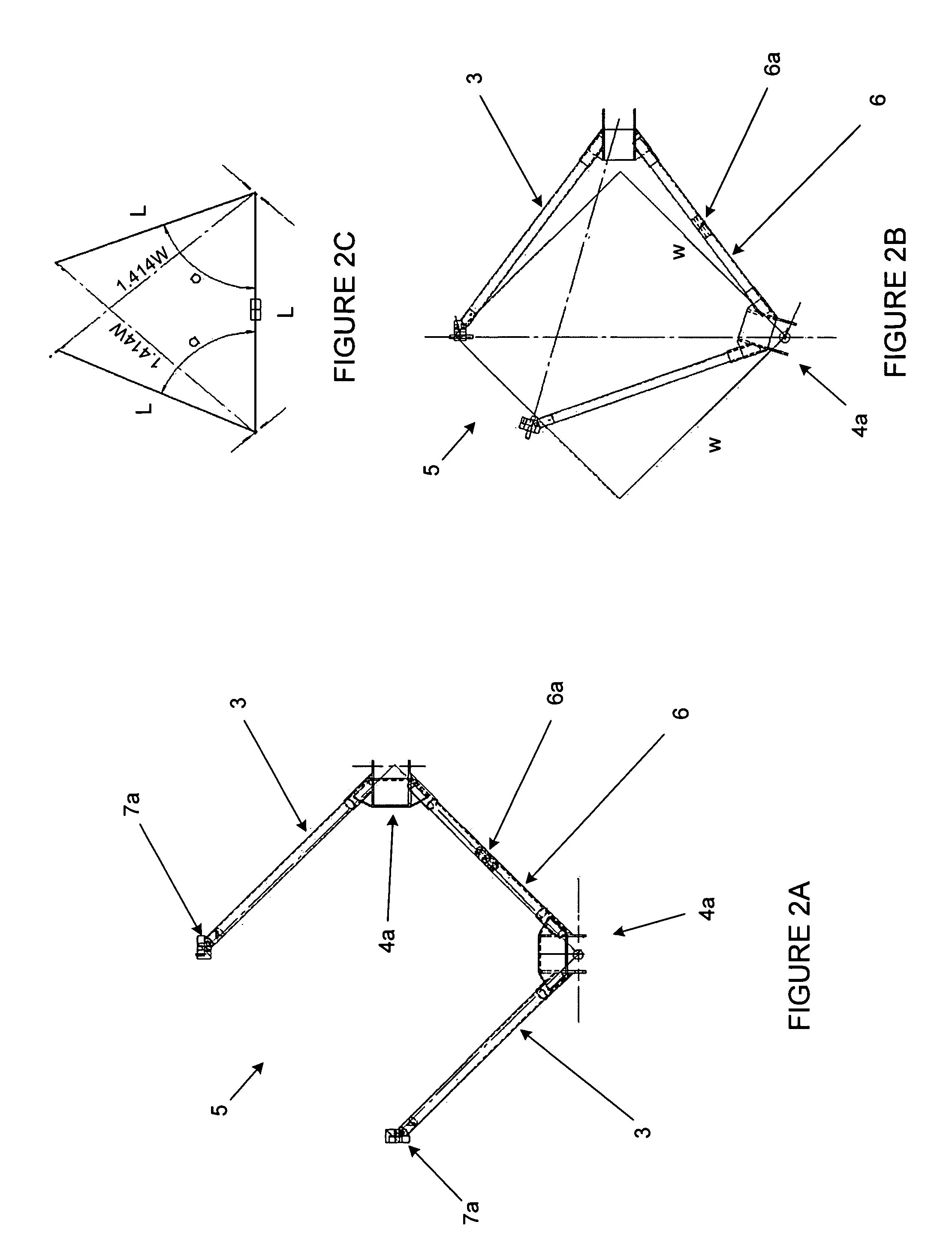
[0019]The primary chords 1 are laterally connected by base diagonal members 6. Each secondary chord 2 is laterally connected with the proximal primary chord 1 by side diagonal members 3. When deployed, as shown in FIG. 1A, the structure is equivalent to three planar trusses of Warren pattern with two common chords.

[0020]Primary orthogonal hinge joints 4 connect the ends of the primary chordal members that form the pr...


PUM


Abstract

A deployable single truss with folding or removable chordal members and diagonals and orthogonal hinge joints for continuous and synchronous retraction and extension, in straight and curved configurations. One or more endframes may be used to close off or mount one of more ends of the deployable trusses. A primary orthogonal hinge joint is used to connect the chordal members and diagonals of the deployable trusses along each primary chord. A secondary orthogonal hinge joint to connect the chordal members and diagonals of the deployable trusses along each secondary chord.

Description

[0001]Be it known that I, Donald V. Merrifield, a citizen of the United States, residing at 703 St. Francis Avenue, Smyrna, Tenn. 37167, have invented a new and useful “Deployable Truss Beam with Orthogonally-Hinged Folding Diagonals,” which is the subject of Provisional Patent Application Ser. No. 60 / 302,997, filed Jul. 3, 2001, by Donald V. Merrifield, and is entitled to that filing date for priority.BACKGROUND OF THE INVENTION[0002]This invention relates generally to deployable truss beams, and more particularly to the apparatus and manner in which a three-dimensional, tetrahedron-based truss of square or rectangular section can be expanded and retracted in a continuous, stable, synchronous fashion in a variety of combinations and configurations to form a load-carrying beam or mast. Four longitudinal truss chords are formed by primary and secondary chord members, which can be formed by hinged, rigid, or flexible members. Chord members are connected by framesets comprised of truss...

Claims


Application Information

Patent Timeline
IPC IPC(8): E04G1/18E04G1/22B64G1/22B64G99/00E04C3/00
CPCB64G1/222E04C3/005B64G9/00B64G99/00B64G1/2224
Inventor MERRIFIELD, DONALD V.
Owner CPI TECH
Why Eureka
Try Eureka