Semiconductor memory device

a memory device and semiconductor technology, applied in the field of semiconductor memory devices, can solve the problems of increasing the difficulty of setting the reference current or the reference voltage, the inability to provide appropriate reference current or reference voltage, and the inability to perform readings, etc., and achieve the effect of low cos

Inactive Publication Date: 2006-04-11
XENOGENIC DEV LLC
View PDF6 Cites 53 Cited by
  • Summary
  • Abstract
  • Description
  • Claims
  • Application Information

AI Technical Summary

Benefits of technology

[0028]The present invention has been made in view of the above problems and it is an object of the present invention to improve a readout margin in consideration of an influence of a leak current which varies with a resistance value of a memory cell to be read, which comprises a variable resistive element storing three or more multi-level information.
[0031]According to the semiconductor memory device of the first characteristic of the present invention, since the current flowing in the row selection line in a middle state of the state in which an influence of the leak current of one resistance state becomes maximum to the other, between any two adjacent resistance states of the states corresponding to the three or more memory levels of the memory cell to be read is set as the reference value and the readout current of the row selection line connected to the memory cell to be read is compared with the reference value, even when the memory level of the memory cell to be read is either of the two resistance states, a maximum readout margin can be provided. That is, even when any memory data of the three or more memory levels is read, the readout margin can be improved.
[0033]According to the semiconductor memory device of the second characteristic of the present invention, since the first reference current generation circuit which approximately implements the first current state and the second reference current generation circuit which approximately implements the second current state at each reference level in the third characteristic can be surely and easily implemented by the two reference memory cell arrays set in the different distribution patterns, the effect of the semiconductor memory device according to the first characteristic of the present invention can be concretely provided.
[0035]According to the semiconductor memory device of the third characteristic of the present invention, since the first reference current generation circuit which approximately implements the first current state and the second reference current generation circuit which approximately implements the second current state are used among the plurality of memory cell arrays in common, a relative circuit size (that is, an occupied area on a semiconductor chip) of the first reference current generation circuit and the second reference current generation circuit can be reduced, so that the semiconductor memory device can be manufactured at low cost.

Problems solved by technology

However, since the leak current in the same direction or in the opposite direction to the readout current exists in addition to variation in resistance value of the selected memory cell itself, when the reference current or the reference voltage is simply set at the middle value of the readout current or its converted voltage provided from the standard resistance value corresponding to each memory level of the selected memory cell, it is highly possible that the appropriate reference current or reference voltage cannot be provided because of the leak current.
Therefore, even when the readout margin is provided for reading one memory level, since the readout margin for reading the other memory level becomes small, the reading cannot be performed if the worst case comes to the worst.
Especially, when the memory cell stores three or more multi-level information, an influence by the leak current becomes large and it becomes more difficult to set the reference current or the reference voltage.
That is, since the leak current caused by the voltage fluctuation of the data line is increased, when the memory cell stores three or more multi-level information especially, the influence of the leak current is increased and the readout of the memory cell becomes more difficult or becomes impossible.

Method used


Image

  • Semiconductor memory device
  • Semiconductor memory device
  • Semiconductor memory device

Examples


second embodiment

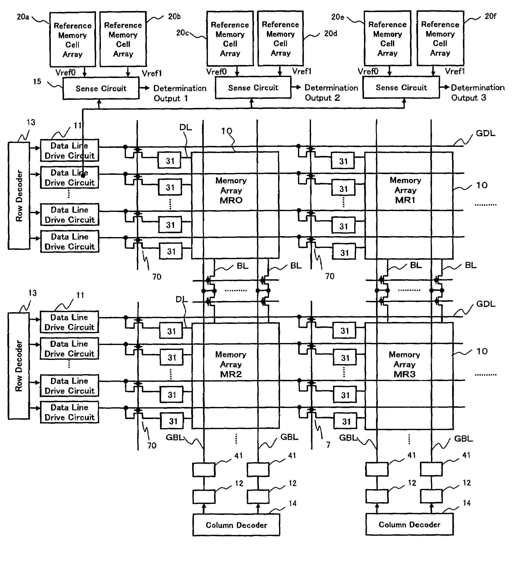
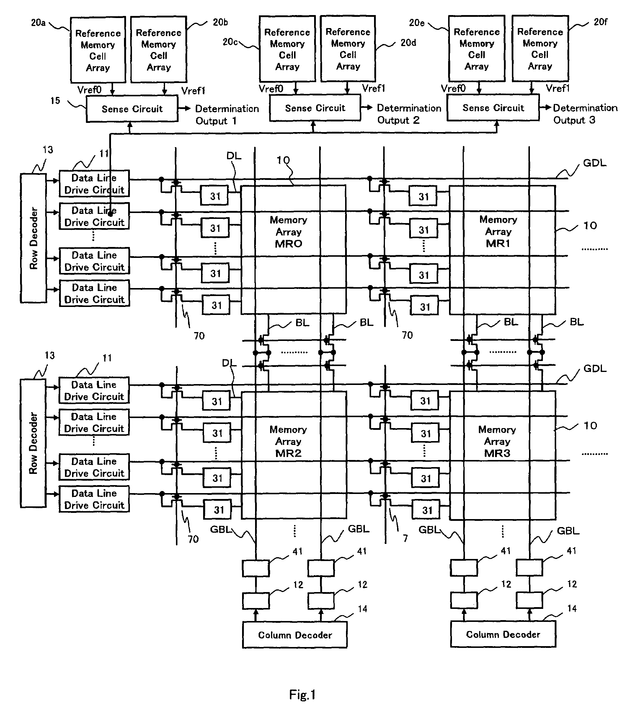
[0132]Although a description was made of a case where when the 4-level data of one memory cell is read out by selecting one data line from a selected memory cell array, the three sense circuits 15 are used in parallel to compare its voltage level with three reference levels at the same time according to the first embodiment as shown in FIG. 1, according to this embodiment, a description will be made of a case where one sense circuit 15 is used to change over three reference levels in terms of time in rotation.

[0133]According to the readout method in the first embodiment, as shown in FIG. 25, the middle current level between the upper limit value of the readout current of the high resistance memory cell generated in the reference memory cell array when the high resistance memory cell is selected, and the lower limit value of the readout current of the low resistance memory cell generated in the reference memory cell array when the low resistance memory cell is selected is generated, ...


PUM


Abstract

In a semiconductor memory device having a crosspoint-type memory cell array, each reference level between two adjacent memory levels when memory levels of multi-level information stored in a memory cell are arranged in order of size of resistance values of a corresponding variable resistive element is defined by a reference current in a middle state between a first and a second current states. In the first current state, a readout current of high resistance selected cell in which the resistance is higher in the two adjacent memory levels becomes the largest state depending on a distribution pattern of a resistance state of the other unselected cell. In the second current state, a readout current of low resistance selected cell in which the resistance is lower in the two adjacent memory levels becomes a smallest state depending on a distribution pattern of a resistance state of the other unselected memory cell.

Description

CROSS REFERENCE TO RELATED APPLICATION[0001]This Nonprovisional application claims priority under 35 U.S.C. §119(a) on Patent Application No. 2004-177503 filed in Japan on Jun. 15, 2004, the entire contents of which are hereby incorporated by reference.BACKGROUND OF THE INVENTION[0002]1. Field of the Invention[0003]The present invention relates to a semiconductor memory device having a crosspoint-type memory cell array in which memory cells are arranged in a row direction and a column direction, one ends of the respective memory cells in the same row are connected to the same row selection line, and the other ends of the respective memory cells are connected to the same column selection line. More particularly, the present invention relates to a semiconductor memory device in which a memory cell comprises a variable resistive element which stores three or more multi-level information depending on a change in electric resistance.[0004]2. Description of the Related Art[0005]Recently, ...

Claims


Application Information

Patent Timeline
Patent Type & Authority Patents(United States)
IPC IPC(8): G11C7/02G11C8/08G11C11/16G11C11/22G11C11/34G11C11/56G11C13/00G11C16/02
CPCG11C8/08G11C11/16G11C11/22G11C11/5678G11C11/5685G11C13/0007G11C13/0028G11C13/004G11C13/0004G11C2213/77G11C2013/0054G11C2213/31G11C5/14G11C7/06G11C13/0016G11C13/0038
Inventor INOUE, KOJI
Owner XENOGENIC DEV LLC
Why Eureka
Try Eureka