
Liquid flow proximity sensor for use in immersion lithography

a proximity sensor and immersion lithography technology, applied in flow control, liquid/fluent solid measurement, instruments, etc., can solve the problems of significant challenges associated with creating a proximity sensor of such accuracy, serious shortcomings of sensors, degrade or ruin semiconductor quality, etc., and achieve the effect of enhancing the ability of a proximity sensor

Inactive Publication Date: 2006-04-04
ASML HLDG NV
View PDF21 Cites 22 Cited by
  • Summary
  • Abstract
  • Description
  • Claims
  • Application Information

AI Technical Summary

Benefits of technology

The solution provides high-resolution distance measurement independent of wafer material properties, suitable for immersion photolithography, ensuring precise and contamination-free proximity sensing, enhancing the accuracy and reliability of semiconductor fabrication.

Problems solved by technology

The challenges associated with creating a proximity sensor of such accuracy are significant, particularly in the context of photolithography systems.
Occurrence of either situation may significantly degrade or ruin the semiconductor quality.
These proximity sensors have serious shortcomings when used in photolithography systems because physical properties of materials deposited on wafers may impact the precision of these devices.
For example, capacitance gauges, being dependent on the concentration of electric charges, can yield spurious proximity readings in locations where one type of material (e.g., metal) is concentrated.
Another class of problems occurs when exotic wafers made of non-conductive and / or photosensitive materials, such as Gallium Arsenide (GaAs) and Indium Phosphide (InP), are used.
In these cases, capacitance and optical gauges may provide spurious results.
Furthermore, as imaging requirements within lithography methods become more challenging, one alternative approach being used is immersion lithography.
Air gauge sensors, such as those disclosed in U.S. Pat. Nos. 4,953,388 and 4,550,592, would be ineffective in an immersion lithography system.

Method used


Image

  • Liquid flow proximity sensor for use in immersion lithography
  • Liquid flow proximity sensor for use in immersion lithography
  • Liquid flow proximity sensor for use in immersion lithography

Examples


Embodiment Construction

[0032]While the present invention is described herein with reference to illustrative embodiments for particular applications, it should be understood that the invention is not limited thereto. Those skilled in the art with access to the teachings provided herein will recognize additional modifications, applications, and embodiments within the scope thereof and additional fields in which the present invention would be of significant utility.

A. Liquid Flow Proximity Sensor

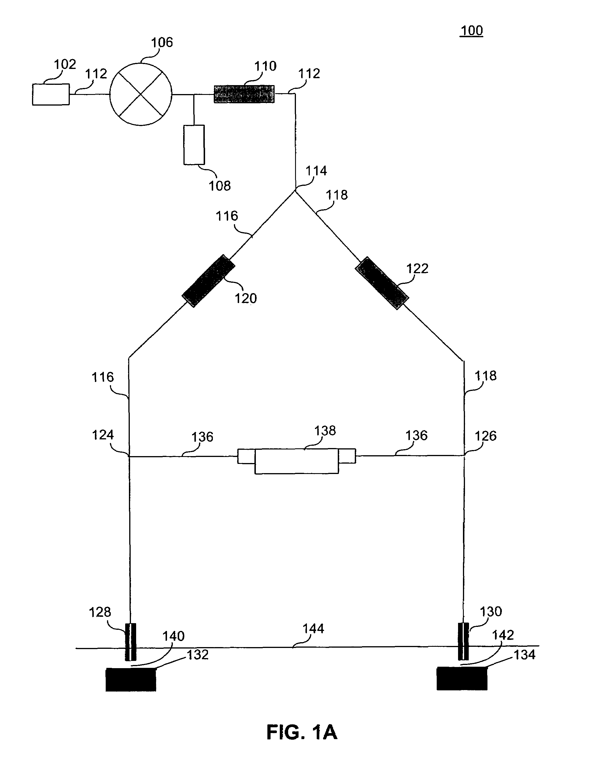
[0033]FIG. 1A illustrates liquid flow proximity sensor 100, according to an embodiment of the present invention. Liquid flow proximity sensor 100 includes liquid mass flow controller 106, central channel 112, measurement channel 116, reference channel 118, measurement channel restrictor 120, reference channel restrictor 122, measurement probe 128, reference probe 130, bridge channel 136 and liquid mass flow sensor 138. Liquid supply 102 injects a liquid at a desired pressure into liquid flow proximity sensor 100. The...


PUM

PropertyMeasurementUnit
lengthaaaaaaaaaa
inner diameteraaaaaaaaaa

Abstract

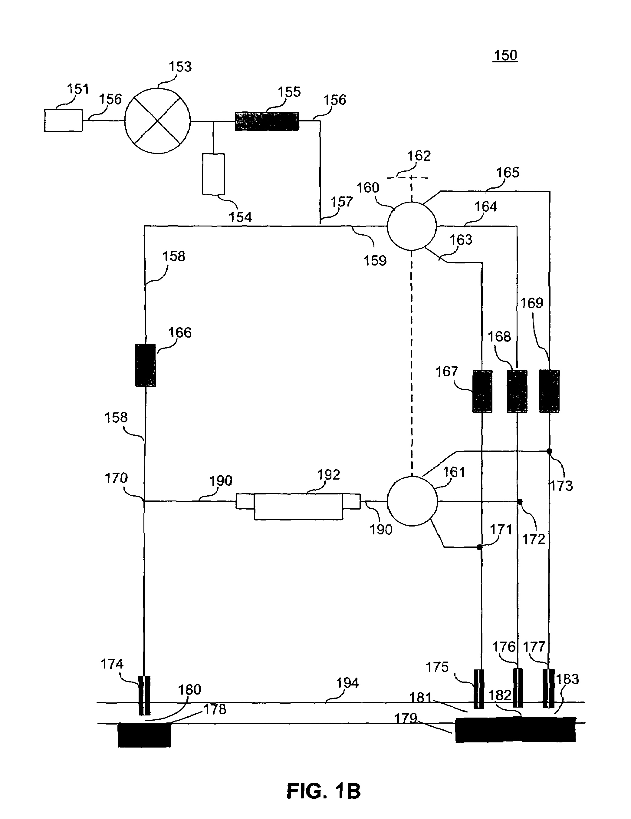
An apparatus and method for precisely detecting very small distances between a measurement probe and a surface, and more particularly to a proximity sensor using a constant liquid flow and sensing a liquid mass flow rate within a bridge to detect very small distances. Within the apparatus the use of a flow restrictor and / or snubber made of porous material and / or a liquid mass flow rate controller enables detection of very small distances in the nanometer to sub-nanometer range. A further embodiment wherein a measurement channel of a proximity sensor is connected to multiple measurement branches.

Description

CROSS REFERENCE TO RELATED APPLICATIONS[0001]This application is a continuation in part of application Ser. No. 10 / 322,768, filed Dec. 19, 2002, which is incorporated herein in its entirety.BACKGROUND OF THE INVENTION[0002]1. Field of the Invention[0003]The present invention relates to an apparatus and method for detecting very small distances, and more particularly to proximity sensing with liquid flow.[0004]2. Related Art[0005]Many automated manufacturing processes require the sensing of the distance between a manufacturing tool and the product or material surface being worked. In some situations, such as semiconductor lithography, the distance must be measured with accuracy approaching a nanometer.[0006]The challenges associated with creating a proximity sensor of such accuracy are significant, particularly in the context of photolithography systems. In the photolithography context, in addition to being non-intrusive and having the ability to precisely detect very small distances...

Claims


Application Information

Patent Timeline
Patent Type & Authority Patents(United States)
IPC IPC(8): G01B13/08G01F1/00G01B13/12G03F7/20G05D7/01H01L21/027
CPCG01B13/12G03F7/70341G05D7/0186G03F7/709G03F7/7085B82Y35/00
Inventor VIOLETTE, KEVIN J.
Owner ASML HLDG NV
Learn More