Eureka AIR delivers breakthrough ideas for toughest innovation challenges, trusted by R&D personnel around the world.

Adapter and analyzer device for performing X-ray fluorescence analysis on hot surfaces

a technology of fluorescence analysis and analyzer, which is applied in the direction of instruments, radiation measurement, x-ray apparatus, etc., can solve the problems of inability to provide reliable results, unattractive obvious solution, and relatively low efficiency of thermoelectric cooling, etc., to achieve low thermal conductivity, improve thermal bridge, and look sleek

Active Publication Date: 2006-03-28
HITACHI HIGH TECH ANALYTICAL SCI FINLAND OY
View PDF5 Cites 49 Cited by
  • Summary
  • Abstract
  • Description
  • Claims
  • Application Information

AI Technical Summary

Benefits of technology

[0008]An objective of the present invention is to provide temperature protection to an X-ray fluorescence analyzer device. This objective should be achieved in a way that is advantageous from manufacturing point of view and cost-effective, and places little restrictions to the other viewpoints that must be considered in designing the device.
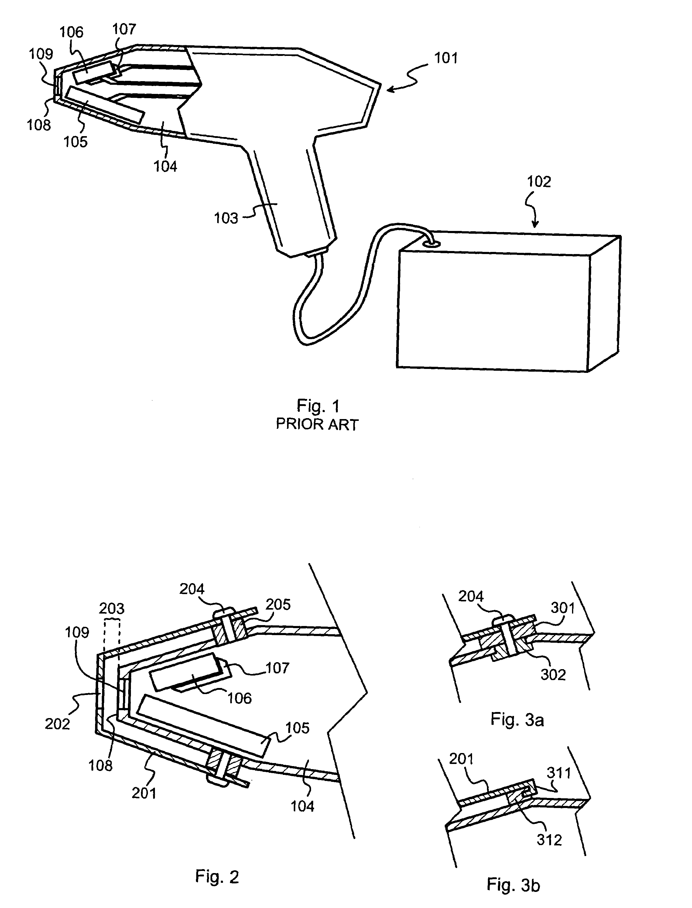
[0014]According to the invention, an adapter is placed between the front end of a measurement head and the surface of the target to be measured. For convenience it is most advantageous to have the adapter at least semipermanently fixed to the measurement head, so that it does not need to be handled separately. The adapter defines an auxiliary surface, which is to be pressed against the target to be analysed. Behind this auxiliary surface there is most advantageously a thermally insulating layer, such as an air gap or a layer of a thermally insulating solid material, which separates the adapter from the front end of the measurement head. Also the material of the adapter proper has most advantageously as low thermal conductivity as possible, taken account however that it must stand high temperatures and also be mechanically durable. A hole or window in the adapter allows incident X-rays and fluorescent radiation to pass through.
[0015]Beyond the part that defines said auxiliary surface it is usually most advantageous to make the adapter conform to the form of the outer surface of the measurement head. One advantage gained therethrough is sleek appearance: the adapter does not change much the overall outer appearance of the measurement head, and does not constitute protrusions that might make the device too bulky for field use. Another advantage is that the mechanical attachment of the adapter to the measurement head can be accomplished at a location relatively far from the part that will be in contact with the hot target surface, which lengthens the thermal bridge between the target and the body of the measurement head and consequently slows down the conduction of heat.
[0016]It is possible, however, to extend the adapter so that it will shield the user, or at least his hand, from heat radiated by the target. The same shielding function might also help to increase protection against scattered incident X-rays.

Problems solved by technology

If the ambient temperature increases beyond a certain threshold, not even a maximum effort made by the cooling arrangement 107 will be sufficient to keep the detector 106 from reaching a cut-off temperature at which it will not be able to provide reliable results any more.
However, such an obvious solution is unattractive especially from the viewpoint of power management.
Thermoelectric cooling has relatively low efficiency (at least concerning the implementations known at the time of writing this description), which means that it draws a relatively high amount of electric power.
In a portable analyzer device electric power comes from (rechargeable) batteries, so increasing power consumption will inevitably shorten battery life and thus decrease usability.
However, the outer cover is there also for other purposes than for temperature shielding, and these other purposes may place other requirements to the material that are even contradictory to low thermal conductivity or at least require making compromises.
The measurement geometry will not be the same as in a press-against measurement, which will introduce a systematic error to the results.
Additionally some X-ray radiation might escape into unwanted directions, which causes a small but not insignificant radiation hazard if the user of the device is not careful.

Method used


Image

  • Adapter and analyzer device for performing X-ray fluorescence analysis on hot surfaces
  • Adapter and analyzer device for performing X-ray fluorescence analysis on hot surfaces
  • Adapter and analyzer device for performing X-ray fluorescence analysis on hot surfaces

Examples


Embodiment Construction

[0025]FIG. 2 is a partial cut-out diagram of a part of a portable X-ray fluorescence analyzer device equipped with an adapter according to an embodiment of the invention. The front part of the component compartment 104, as well as the X-ray source 105, detector 106 and cooling arrangement 107 are visible in the drawing. Supported in front of the front end 108 is an adapter 201, which is basically a sheet of material having certain advantageous qualities such as low thermal conductivity, bent to a three-dimensional shape in which is roughly follows the form of those parts of the analyzer device it covers. A hole 202 in the adapter coincides with the window 109 in the front end 108 of the analyzer device. A thermally insulating layer, which in the embodiment of FIG. 2 is an air gap 203 but which could also be a layer of a thermally insulating solid material, separates the adapter 201 from the front end 108 of the measurement head. In this exemplary embodiment the thickness of said the...


PUM

PropertyMeasurementUnit
temperaturesaaaaaaaaaa
thicknessaaaaaaaaaa
surface temperatureaaaaaaaaaa

Abstract

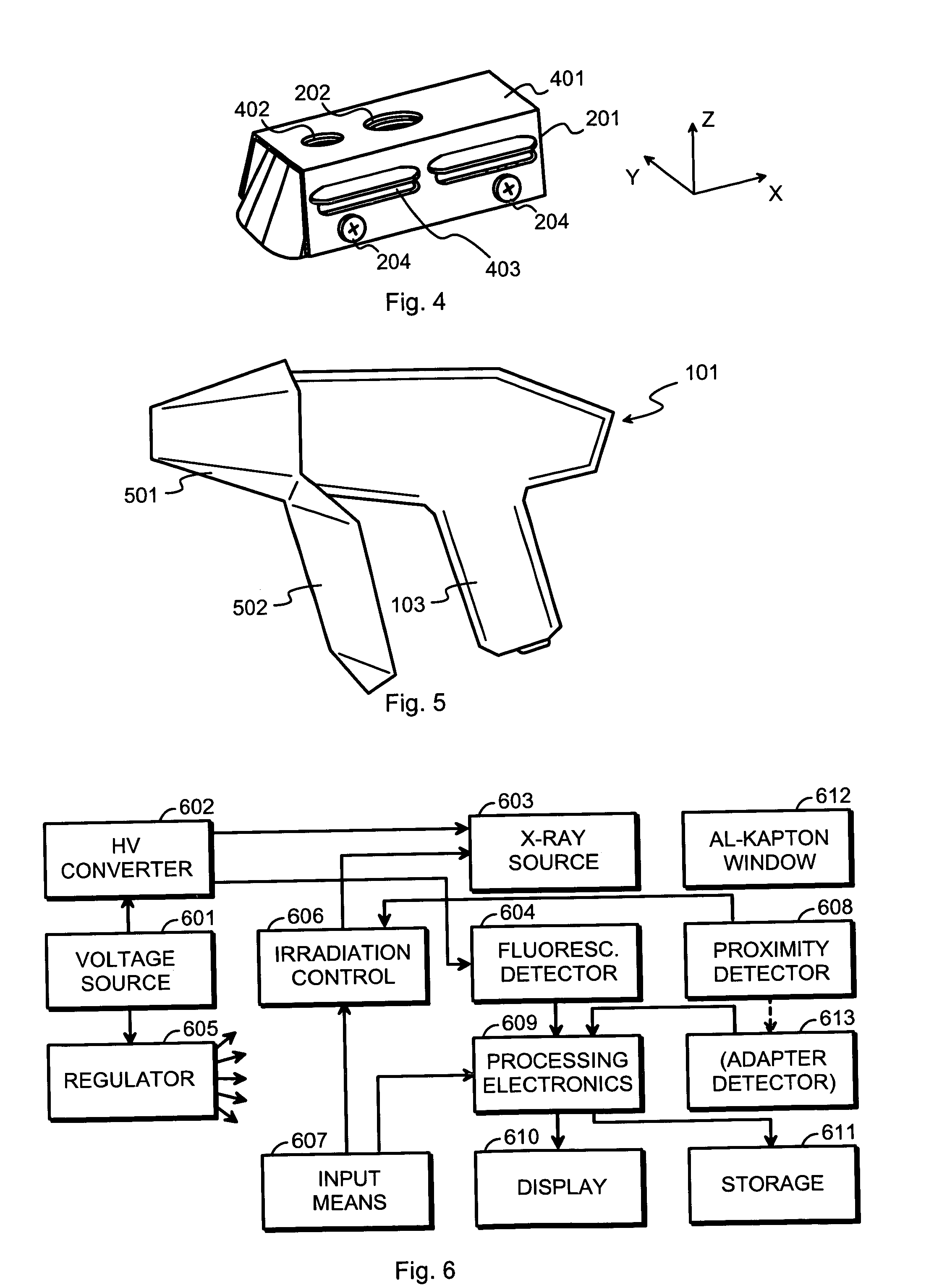
The measurement head (101) of an X-ray fluorescence analyzer device is protected against heat from a hot target by using an adapter (201). It comprises a sheet of material having low thermal conductivity and has a three-dimensional shape that follows the form of a front part of the measurement head (101). Said sheet of material is attached to said measurement head (101) and has a central part (401) which defines an opening (202) coincident with a radiation window (109) in said measurement head (101). Said attachment means (204, 205, 301, 302, 311, 312) are located at a part of said sheet of material that is distant from said central part (401).

Description

TECHNICAL FIELD[0001]The invention concerns generally the technology of performing X-ray fluorescence analysis of objects using a portable analyzer device. Especially the invention concerns protecting the analyzer device and potentially also its user against excess heat when the object to be analyzed is hot.BACKGROUND OF THE INVENTION[0002]X-ray fluorescence analysis is a general designation of all techniques based on irradiating a target with X-rays, collecting fluorescent radiation induced in said target by said X-rays and drawing conclusions about the characteristics of said target on the basis of the intensity and frequency spectrum of the fluorescent radiation. Common applications of X-ray fluorescence analysis include investigating the material composition of the target. In many cases the main interest is to determine, how much the target contains some additive, pollutant or other minority constituent that can have important, potentially harmful effects, such as sulphur in liq...

Claims


Application Information

Patent Timeline
Patent Type & Authority Patents(United States)
IPC IPC(8): G01N23/223
CPCG01N23/223G01N2223/076
Inventor KANTONEN, ESKO JUHANIKESALA, JANNE ADOLF PETTERIPUUSAARI, ERKKI TAPANISIPILA, HEIKKI JOHANNES
Owner HITACHI HIGH TECH ANALYTICAL SCI FINLAND OY
Why Eureka
Eureka Blog
Learn More