
Refuse container transporter and lift

Inactive Publication Date: 2006-03-28
SACRAMENTO UNIFIED SCHOOL DISTRICT
View PDF12 Cites 45 Cited by
  • Summary
  • Abstract
  • Description
  • Claims
  • Application Information

AI Technical Summary

Benefits of technology

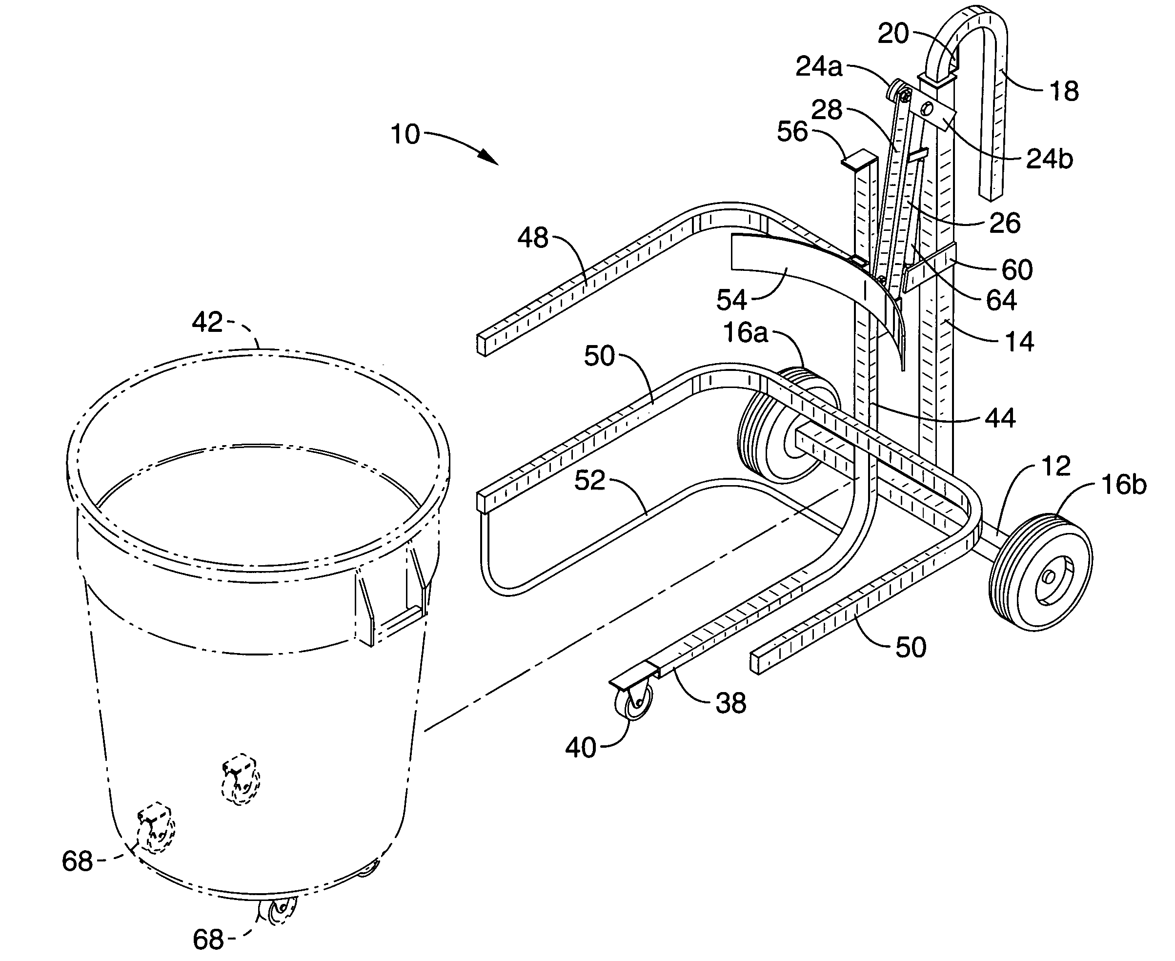
[0012]The present invention is a refuse container transport and lift apparatus that can easily engage a refuse depository, such as a dumpster or refuse chute or the like, and then permit the refuse container to be emptied with little effort. The apparatus allows for transport, and lifting, toward at least partial inversion, of a refuse container for emptying garbage therefrom into a refuse receptacle, or dumpster. The apparatus comprises a frame having at least two wheels adapted to provide rollable transport thereof, a column connected to the frame, a bin carriage adapted for receiving a refuse container, and a plurality of angularly offset parallel pivot arms coupled between the column and the bin carriage. In response to an applied pivot force, manually or from a mechanical power unit, the bin carriage is guided by the pivot arms upwardly and is rotated toward at least partial inversion of the bin carriage and retained refuse container for emptying waste into a dumpster or other refuse receptacle.
[0013]By way of example, and not of limitation, the invention includes a base with a central vertical column and at least two wheels that allow free movement of the base, wherein the apparatus with a received refuse container within a bin carriage may be rollably transported to a large refuse receptacle or the disposal chute which leads into a refuse receptacle. Optional wheels are preferably incorporated under the bin carriage, which also supports the load of the refuse container, and aids in stabilizing the apparatus while allowing for movement without the need to tilt the apparatus during transport. At least one pair of parallel lever arms are pivotally coupled to the base at one end and pivotally coupled to a bin carriage at the other end. The bin carriage is configured for retaining the refuse bin during the lifting operation. In the preferred embodiment, the lever arms are mounted to an angled mount, or bracket, near the top of the vertical column such that the distal end of the lever arms are linearly offset. The bin carriage is preferably configured to allow for the receipt of an assortment of refuse container sizes, including containers which already incorporate wheels on their bases. At least one long stroke cylinder is preferably utilized to control motion between the bin carriage and the vertical component of the base. The long stroke cylinder may be coupled at various locations, such as between at least one lever arm and the base, for dampening the pivotal movements of the lever arms, or additionally to reduce the forces required when lifting the bin carriage subject to a loaded refuse container.

Problems solved by technology

A failure to retain the receptacle within the bin carriage when emptying refuse would require retrieval, emptying, and cleaning of the refuse container before it could be put to further use.

Method used


Image

  • Refuse container transporter and lift
  • Refuse container transporter and lift
  • Refuse container transporter and lift

Examples


Embodiment Construction

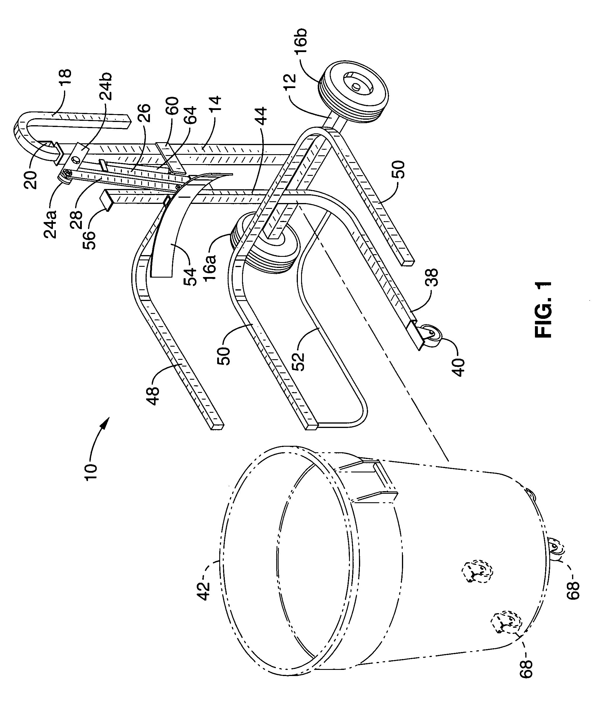
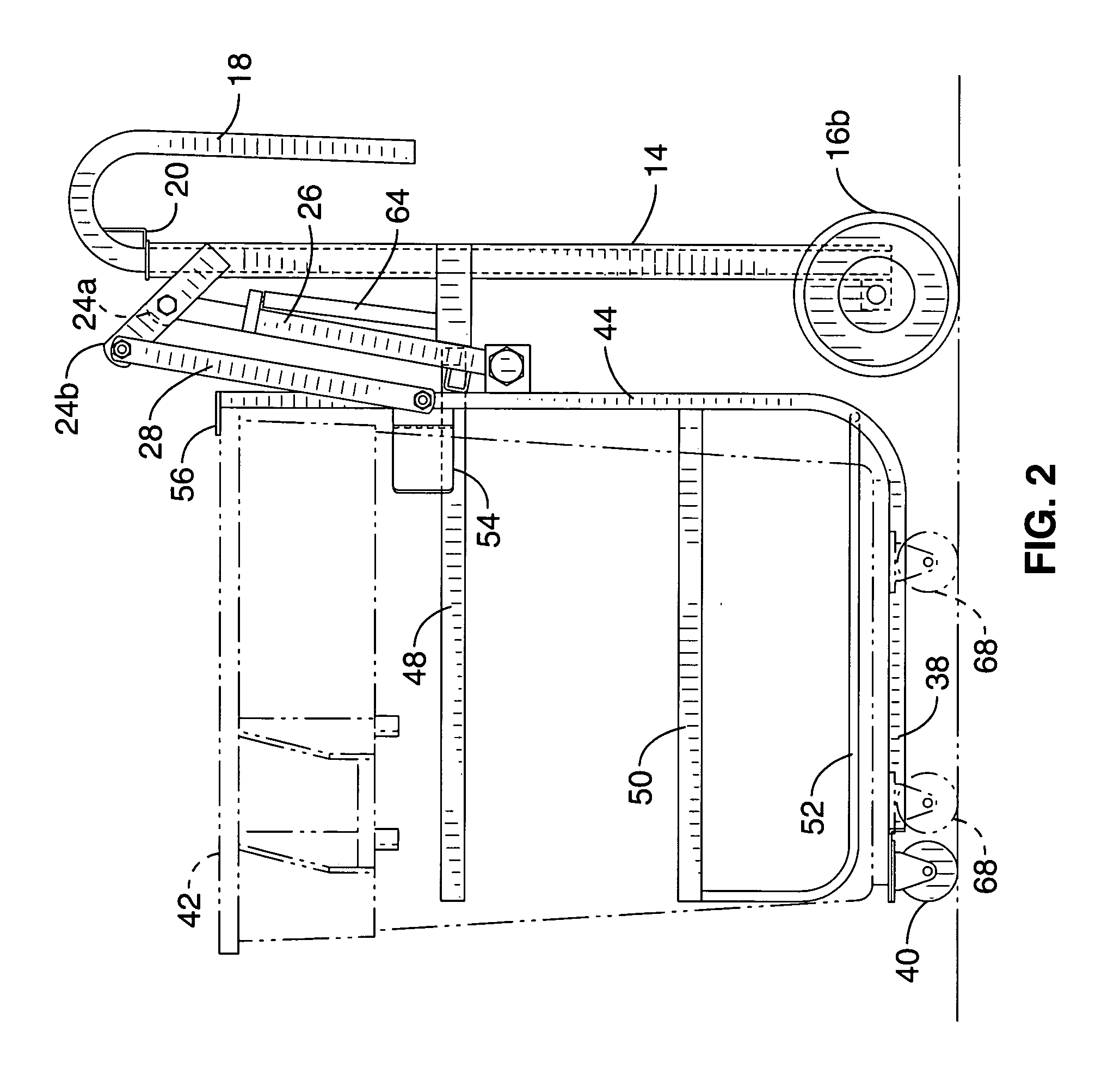
[0039]Referring more specifically to the drawings, for illustrative purposes the present invention is embodied in the apparatus generally shown in FIG. 1 through FIG. 9, where like reference numbers denote like parts. It will be appreciated that the apparatus may vary as to configuration and as to details of the parts without departing from the basic inventive concepts disclosed herein. The disclosed embodiment of the invention is configured for transporting and lifting a generally cylindrical container such as a conventional wheeled, or unwheeled waste container, also commonly referred to as a garbage can. While a generally cylindrical container is considered for purposes of illustration, it will be understood that the apparatus may be configured to transport and lift containers of essentially any shape.

[0040]Referring first to FIG. 1, the invention 10 comprises a horizontal base 12 that preferably has a vertical column 14 mounted centrally thereon. In the embodiment shown, the bas...


PUM


Abstract

A lift apparatus for conveying, lifting and at least partially inverting a refuse container for emptying into a dumpster or a refuse receptacle. The apparatus preferably has a base with wheels and a handle to facilitate transport. In one embodiment, the handle telescopes vertically and is hook shaped and adapted for engaging the lip of a dumpster or garbage chute. A pair of offset pivot arms is pivotally mounted to the frame and to a bin carriage, into which a refuse receptacle may be received. Application of a pivoting force to the pivot arms lifts and at least partially inverts the bin carriage for emptying the refuse container. Preferably a damper is provided on bin carriage movement as well as a locking mechanism to prevent bin carriage movement while being conveyed. The device may be operated manually, or adapted with mechanical power output devices to simplify lifting.

Description

CROSS-REFERENCE TO RELATED APPLICATIONS[0001]This application claims priority from U.S. Provisional Application Ser. No. 60 / 355,179 filed on Feb. 8, 2002, incorporated herein by reference.STATEMENT REGARDING FEDERALLY SPONSORED RESEARCH OR DEVELOPMENT[0002]Not ApplicableREFERENCE TO A COMPUTER PROGRAM APPENDIX[0003]Not ApplicableBACKGROUND OF THE INVENTION[0004]1. Field of the Invention[0005]This invention pertains generally to container transporting devices, and more particularly to a portable refuse container transporter and lifting apparatus that permits the user to transport a waste container to a refuse repository, such as a dumpster or a chute for receiving refuse, and easily lift and invert the container to empty its contents into the dumpster or chute.[0006]2. Description of the Background Art[0007]The disposal of waste materials in many settings typically involves the manual placement of refuse in cylindrical refuse containers of various volumes. The contents of such refuse...

Claims


Application Information

Patent Timeline
IPC IPC(8): B65B21/02
CPCB62B3/0606B62B3/08B62B3/104B65G65/23B65F1/1452B65F1/1473B62B2203/10B62B2202/20B65F1/12
Inventor HEBERLING, JAMES R.REMUND, RICHARD C.
Owner SACRAMENTO UNIFIED SCHOOL DISTRICT
Learn More