
Connection-member for electrical connection of battery cells

Active Publication Date: 2010-10-07
LG ENERGY SOLUTION LTD
View PDF20 Cites 48 Cited by
  • Summary
  • Abstract
  • Description
  • Claims
  • Application Information

AI Technical Summary

Benefits of technology

[0008]Specifically, it is an object of the present invention to provide a connection member that is capable of effectively interconnecting electrode terminals of battery cells through a simple assembly process.
[0021]The shape of the upper case and the lower case is not particularly restricted. Consequently, it is possible to manufacture the upper case and the lower case in various shapes. For example, the upper case and the lower case may be coupled with each other in a hexahedral structure such that the battery cells are stably stacked between the upper case and the lower case. Also, the upper case and the lower case may be manufactured in the same shape such that the upper case and the lower case are coupled with each other in a symmetrical structure. In this case, the upper case and the lower case may be coupled with each other without making a distinction between the upper case and the lower case during the assembly of the pack case, whereby high assembly efficiency is accomplished.
[0028]In this structure, the coupling protrusions, which are formed at the outer surface of the pack case, may be easily engaged in the corresponding coupling grooves, which are formed at the connection part of the connection member, for example, in a forced fitting fashion.

Problems solved by technology

However, the welding or soldering operation is an operation that requires a sophisticated technique, and therefore, it is necessary to secure skilled technicians and a large work space.
Especially when physical impacts are applied to the battery cells, electric short circuits may occur in the battery cells, with the result that the battery cells may catch fire or explode, and therefore, the safety of the battery cells is not guaranteed.
Also, the above-described connection structure needs auxiliary members, such as jigs, to stably fix the plates to the electrode terminals of the unit cells, with the result that the manufacturing costs of the battery pack is increased.

Method used


Image

  • Connection-member for electrical connection of battery cells
  • Connection-member for electrical connection of battery cells
  • Connection-member for electrical connection of battery cells

Examples


Embodiment Construction

[0040]Now, preferred embodiments of the present invention will be described in detail with reference to the accompanying drawings. It should be noted, however, that the scope of the present invention is not limited by the illustrated embodiments.

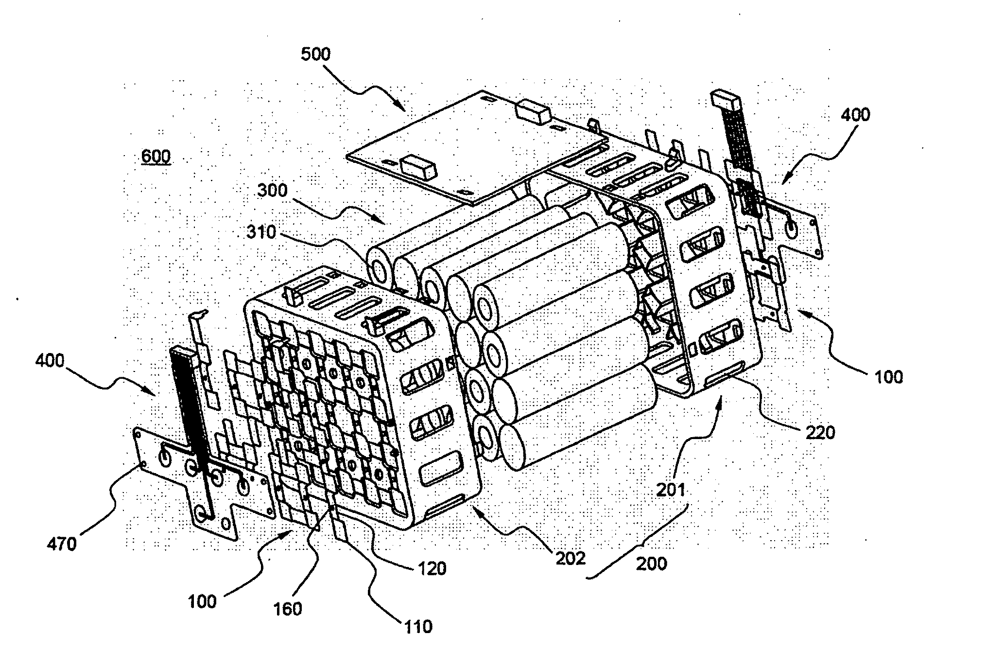
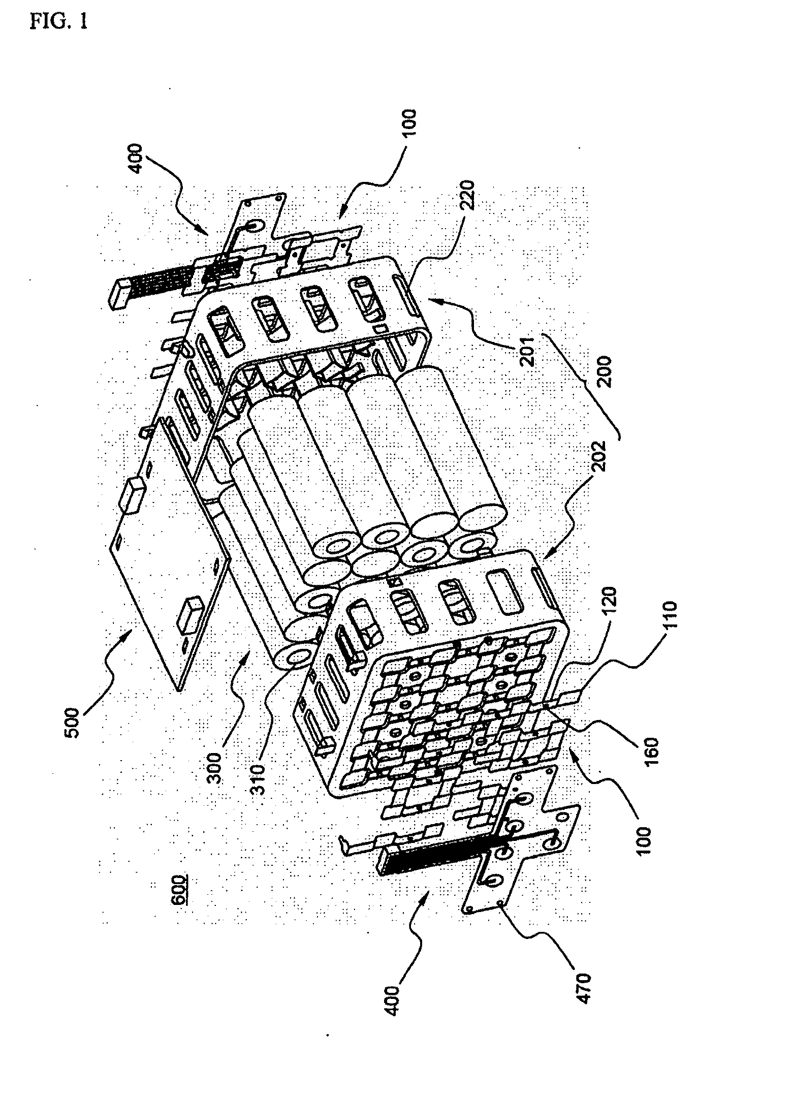
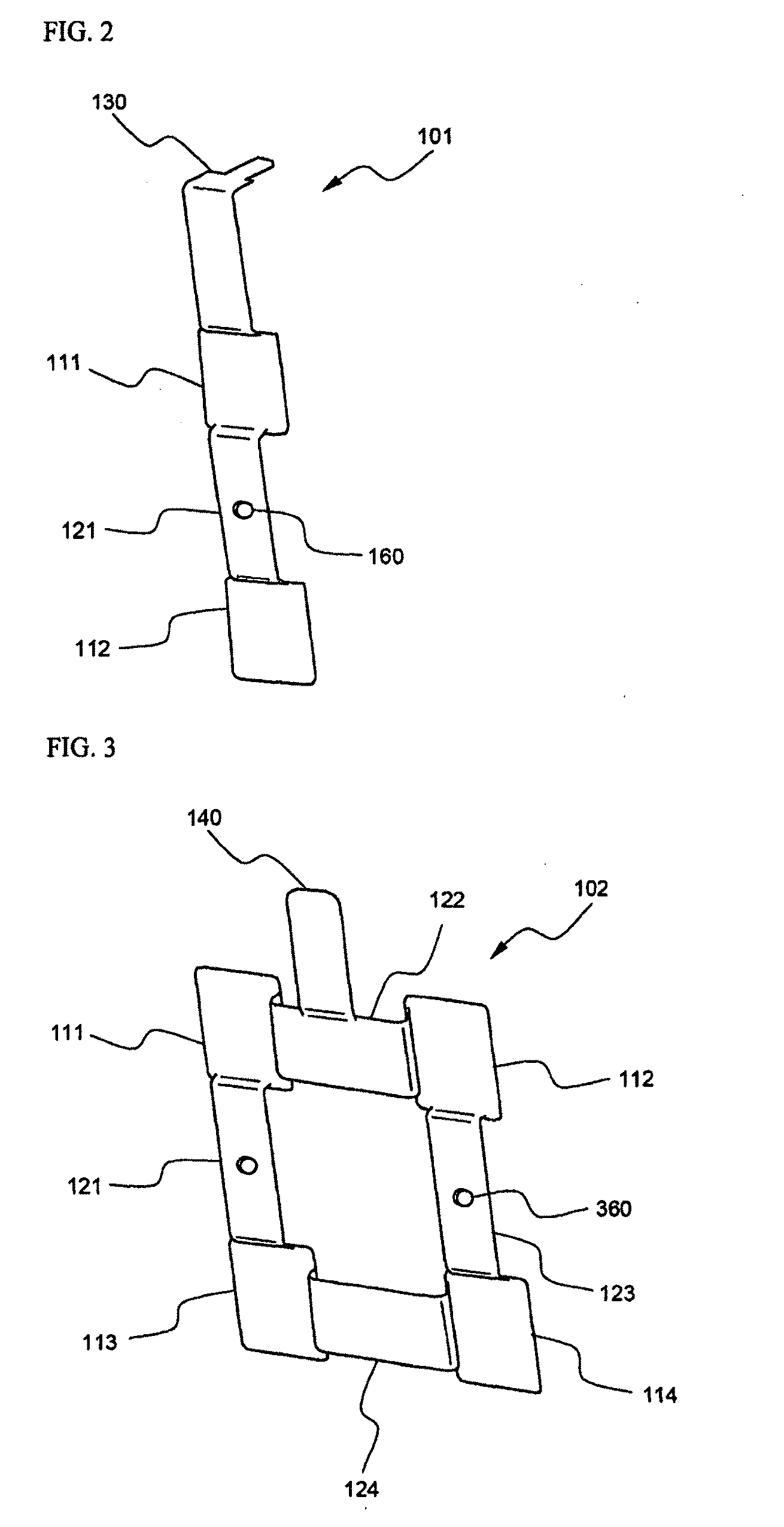
[0041]FIG. 1 is an exploded perspective view illustrating a battery pack including various connection members according to preferred embodiments of the present invention, and FIGS. 2 to 4 are enlarged views illustrating various connection members according to preferred embodiments of the present invention, which are used in the battery pack of FIG. 1.

[0042]Referring to these drawings, the battery pack 600 includes a battery pack case 200 constructed in a structure in which a plurality of cylindrical battery cells 300 are mounted in the battery pack case 200, various metal plates 100 for electrically connecting the battery cells 300 with each other, a flexible printed circuit board (FPCB) 400 connected to the metal plates 100 for detecting vo...


PUM


Abstract

Disclosed herein are a connection member for electrically interconnecting a plurality of battery cells in a battery pack in which the battery cells are mounted, wherein the connection member includes at least two terminal contact parts, which are connected to electrode terminals of neighboring battery cells, and a connection part for interconnecting the terminal contact parts, and wherein the terminal contact parts are lower in height, by a size corresponding to the thickness of a pack case, than the connection part such that the connection member connects the electrode terminals of the battery cells while the connection member is mounted on the outer surface of the pack case, and a battery pack including the same. Consequently, the connection member according to the present invention has the effect of effectively interconnecting the electrode terminals of the battery cells through a simple assembly process. Also, the connection member according to the present invention can be directly mounted on the pack case without using an additional auxiliary member.

Description

FIELD OF THE INVENTION[0001]The present invention relates to a connection member for electric connection between battery cells, and, more particularly, to a connection member for electrically interconnecting a plurality of battery cells in a battery pack in which the battery cells are mounted, wherein the connection member includes at least two terminal contact parts, which are connected to electrode terminals of neighboring battery cells, and a connection part for interconnecting the terminal contact parts, and wherein the terminal contact parts are lower in height, by a size corresponding to the thickness of a pack case, than the connection part such that the connection member connects the electrode terminals of the battery cells while the connection member is mounted on the outer surface of the pack case, and a battery pack including the same.BACKGROUND OF THE INVENTION[0002]As mobile devices have been increasingly developed, and the demand of such mobile devices has increased, t...

Claims


Application Information

Patent Timeline
IPC IPC(8): H01M10/02H01M10/48H01M50/213H01M50/284H01M50/291H01M50/296H01M50/505H01M50/516H01M50/522
CPCH01M2/105H01M2/1077H01M2/204H01M10/5065H01M2/34H01M10/425H01M10/5004H01M2/206H01M10/613H01M10/6562Y02E60/10H01M50/213H01M50/291H01M50/522H01M50/284H01M50/516H01M50/296H01M50/505H01M50/20H01M50/10
Inventor PARK, JONGHOJEON, KI HYUNKANG, BONG HYUPCHO, YONGHOSHIN, JOONYOUNGHUR, MAN-CHULLEE, HAKJUN
Owner LG ENERGY SOLUTION LTD
Learn More