Door lock system for trailers and cargo containers

Inactive Publication Date: 2009-02-03
MOORE GREGORY B
View PDF28 Cites 42 Cited by
  • Summary
  • Abstract
  • Description
  • Claims
  • Application Information

AI Technical Summary

Benefits of technology

[0011]The door lock for trailers and cargo containers of the present invention solves the problems identified above, and provides a new and useful locking device that effectively prevents unauthorized entry through a trailer or container door. The door lock device of the present invention is adaptable to new and existing trailers and containers, is easy for the truck driver or container operator to engage and is difficult for the thief to overcome or disable. The door lock of the present invention automatically engages the locking system when the door is closed and maintains the lock in the locked condition until an authorized person enters the proper unlock code.
[0012]Accordingly, the primary objective of the present invention is to provide a door lock for trailers and cargo containers that provides the advantages described herein and overcomes the disadvantages and / or limitations associated with presently available door lock devices and systems.
[0014]It is also an important objective of the present invention to provide an easy to use and effective theft deterrent system that is difficult to overcome so as to prevent theft of materials from a trailer or cargo container.
[0016]It is also an important objective of the present invention to provide a door lock device for trailers and cargo containers that will maintain a commanded locked or unlocked condition even if power and control are removed from the door lock device.
[0017]It is also an important objective of the present invention to provide a door lock device for trailers and cargo containers that allows for escape for a person inadvertently locked inside of a cargo container.

Problems solved by technology

The door lock device of the present invention is adaptable to new and existing trailers and containers, is easy for the truck driver or container operator to engage and is difficult for the thief to overcome or disable.

Method used


Image

  • Door lock system for trailers and cargo containers
  • Door lock system for trailers and cargo containers
  • Door lock system for trailers and cargo containers

Examples


Embodiment Construction

[0038]With reference to the figures where like elements have been given like numerical designations to facilitate the reader's understanding of the present invention, and particularly with reference to the embodiments of the present invention illustrated in the figures, the preferred embodiments of the present invention are set forth below. The enclosed figures and drawings are merely illustrative of the preferred embodiments and represent several different ways of configuring the present invention. Although specific components, materials, configurations and uses of the present invention are illustrated and set forth in this disclosure, it should be understood that a number of variations to the components and to the configuration of those components described herein and in the accompanying figures can be made without changing the scope and function of the invention set forth herein.

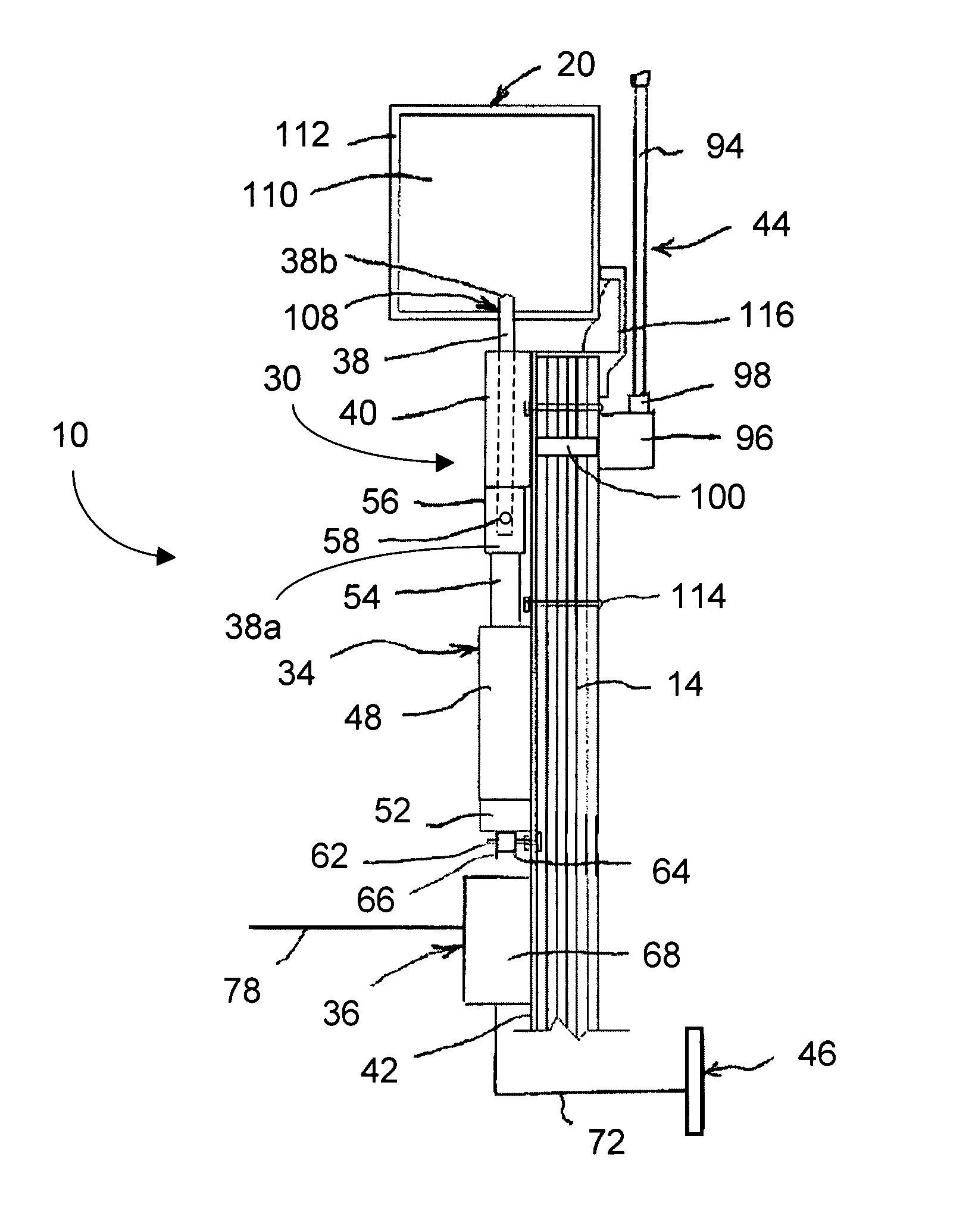
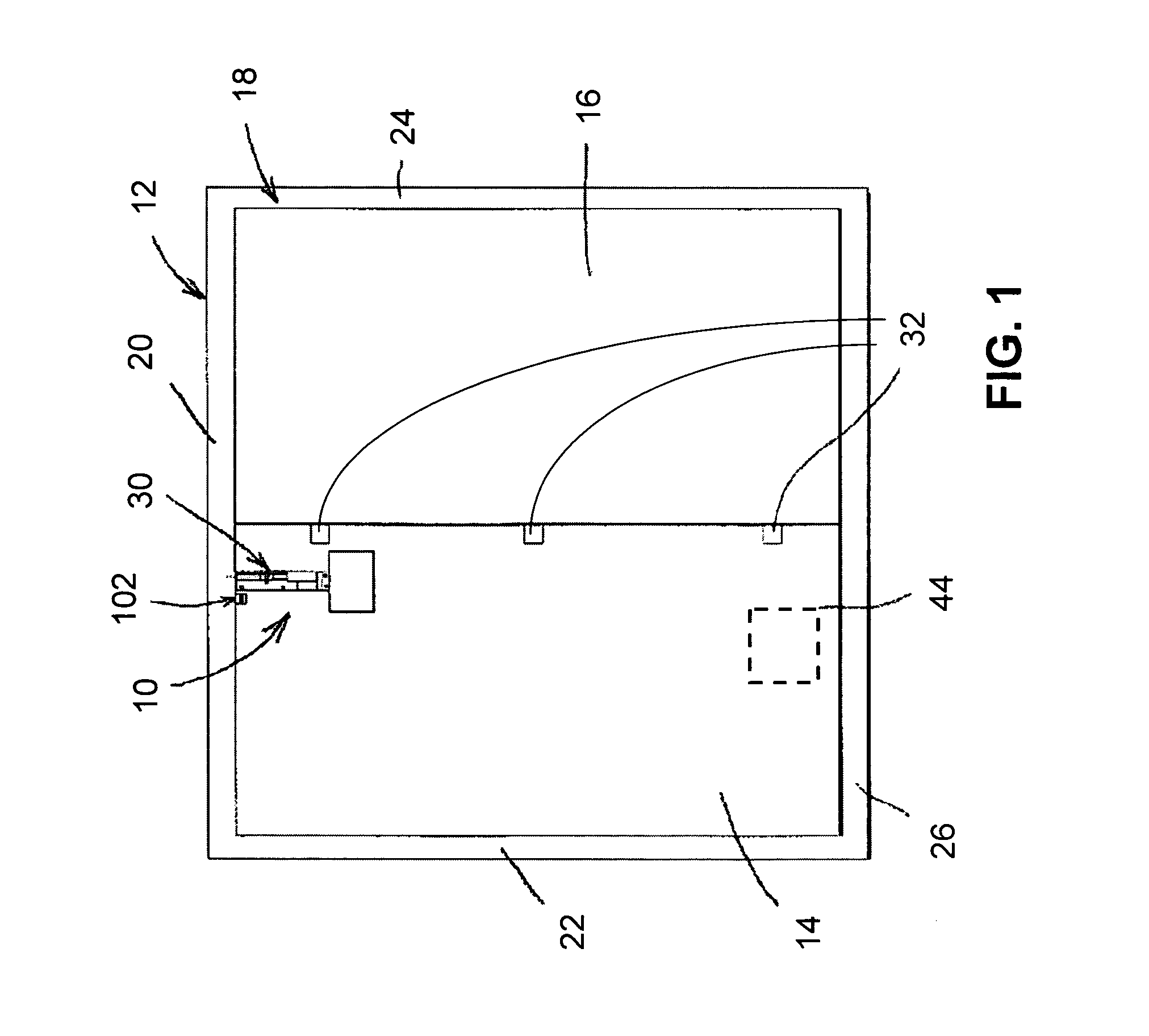
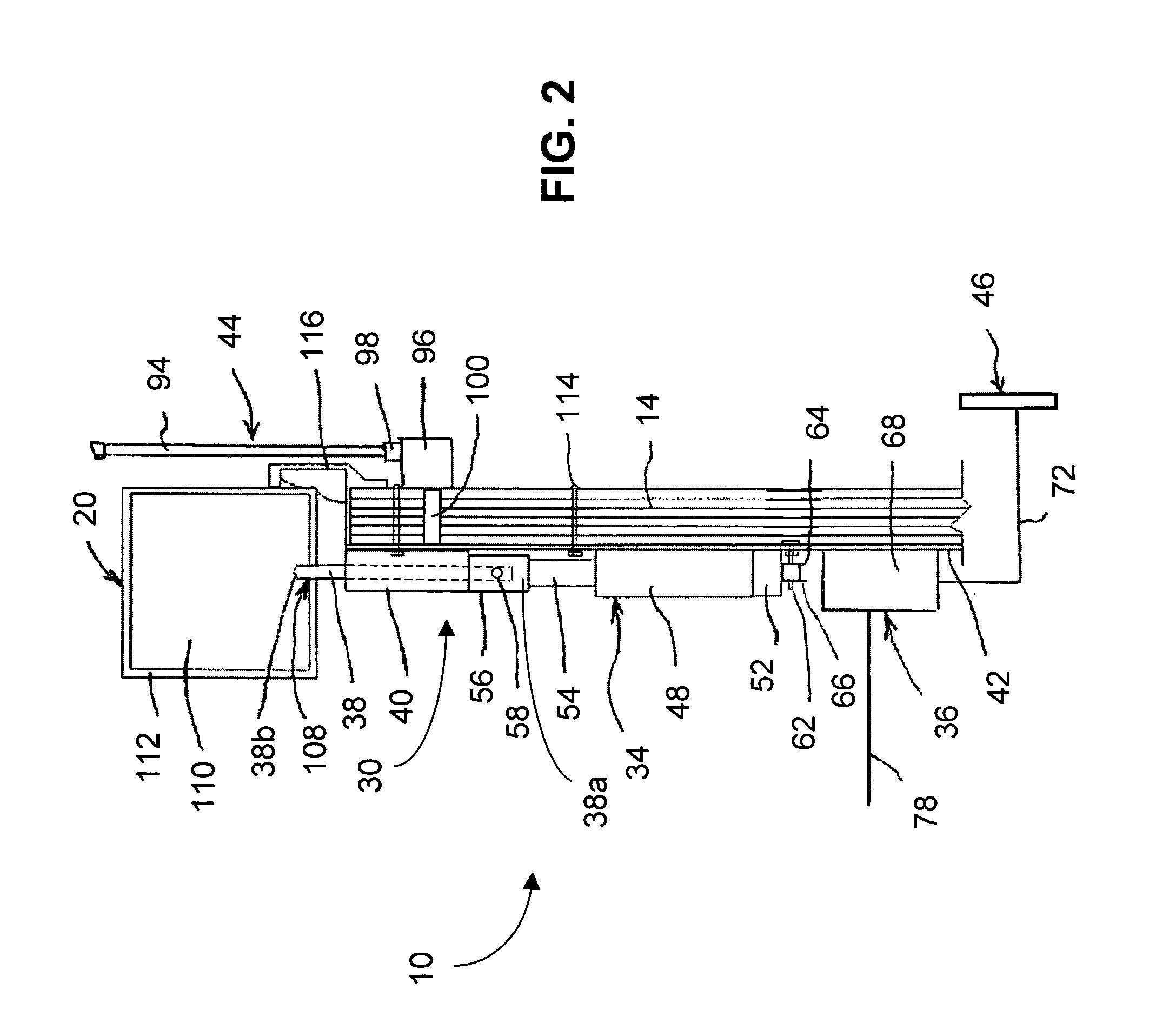
[0039]Referring now to drawings, FIG. 1 shows a door lock system 10, which is configured to function w...


PUM


Abstract

A door lock system for enclosures is provided which includes a screw drive mechanism releasably mounted on a back plate member and coupled via threads to a threaded locking member to linearly drive the locking member to engage with a receptor on an enclosure frame to lock the enclosure. A controller unit has an integrated circuit configured to control the operation of the screw drive mechanism and report the status of the door to a central location. A position switch is used to indicate whether the door is open or closed so that the controller unit can automatically engage the screw drive mechanism to lock the door after a preset time delay. A keypad allows a user to enter a code to unlock the door. A radio in the controller unit permits wireless communication to report status and to allow central command control over the doors.

Description

CROSS-REFERENCE TO RELATED APPLICATION[0001]This is a continuation-in-part of abandoned patent application Ser. No. 10 / 671,187 filed Sep. 24, 2003 now abandoned, the subject matter of which is incorporated herein by this reference, as though set forth in full.BACKGROUND OF THE INVENTION[0002]1. Field of the Invention[0003]The field of the present invention relates generally to computer-controlled lock devices for securing the doors of a trailer or cargo container so as to prevent unauthorized entry into the trailer or container.[0004]2. Description of the Related Art[0005]Many persons utilize trailers and cargo containers for various applications, including trailers and containers that are used to transport goods, vehicles, and other materials. Although the trailers and containers commonly used in the trucking and cargo industry are very expensive, the goods being transported therein, such as electronics or cars, can often far exceed the value of the trailer or container itself. Whi...

Claims


Application Information

Patent Timeline
IPC IPC(8): E05B47/00
CPCB65D90/008B65D90/021E05B47/026E05B83/02E05B39/005E05B81/58E05B81/70G07C9/0069G07C2009/0092B60R2325/205B65D2211/00B65D2590/0083E05B47/0012E05B65/0021E05B2047/0016E05B2047/0023E05B2047/0057E05B2047/0094Y10S292/65Y10T70/5159Y10T70/5367Y10T70/5978Y10T70/7113Y10T70/8027Y10T70/8946Y10T292/0822Y10T292/0908Y10T292/1021Y10T292/1033
Inventor MOORE, GREGORY B.
Owner MOORE GREGORY B
Why Eureka
Try Eureka