
Reduced energy consuming, lateral cutting twist drill

a twist drill and lateral cutting technology, applied in the direction of twist drills, manufacturing tools, wood boring tools, etc., can solve the problem that the twist drill b>10/b> is not configured to accommodate lateral cutting movement in the drilling hole, and achieve the effect of less energy and reduced friction

Inactive Publication Date: 2006-03-28
BITMOORE AN OREGON GEN PARTNERSHIP
View PDF18 Cites 24 Cited by
  • Summary
  • Abstract
  • Description
  • Claims
  • Application Information

AI Technical Summary

Benefits of technology

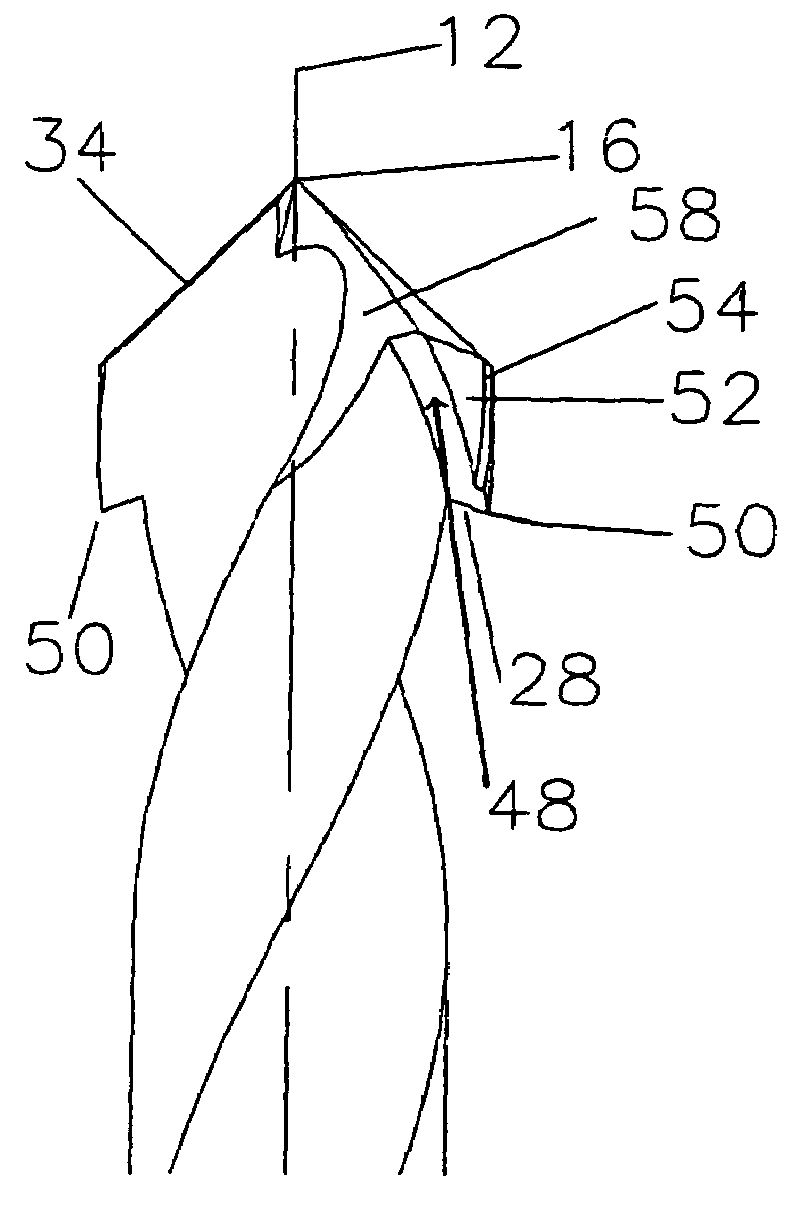
[0006]The present invention provides in a prior art twist drill structural features that require less energy to drill a hole during a normal plunge operation and allow for lateral cutting movement during extraction of the twist drill from a drilled work piece. In a first embodiment, reduced friction is accomplished by provision of a depthwise recess along the length of the shaft between the tapered end and the shank of the twist drill. The recess establishes a transition portion between the tapered end and the shank and thereby determines at the tapered end the lengths of cutting edges angularly inclined from the tip in directions away from the longitudinal axis. The terminations of the inclined cutting edges at the transition portion defines the wall diameter of the hole cut by the twist drill. In a second embodiment, a leading edge tooth formed in the transition portion enables lateral cutting movement during extraction of the twist drill from the work piece.

Problems solved by technology

Moreover, twist drill 10 is not configured to accommodate lateral cutting movement in a drilled hole to facilitate correction of axial misalignment of holes in two work pieces positioned to be joined by a fastener inserted in them.

Method used


Image

  • Reduced energy consuming, lateral cutting twist drill
  • Reduced energy consuming, lateral cutting twist drill
  • Reduced energy consuming, lateral cutting twist drill

Examples


first embodiment

[0015]With particular reference to FIGS. 3B and 3D, the unmodified portion of leading cutting edge 24 of each flute 20 is in the form of an angularly inclined cutting edge 34 and a transition portion cutting edge 36. Inclined cutting edge 34 extends from tip 16 to a termination point 38 at transition portion 30, and transition portion cutting edge 36 follows the spiral direction of flute 20 and is substantially concentric with longitudinal axis 12. Inclined cutting edge 34 is the standard leading sharpened flute edge for conventional plunge operation. FIG. 3D shows cylindrical relief 28 forming a 90 degree relief angle relative to transition portion cutting edge 36; however, other relief angles would be suitable. The radial distance between termination point 38 and longitudinal axis 12 sets the twist drill diameter. FIGS. 3A, 3B, 3C, and 3D show the invention in which the twist drill requires less energy to drill a hole. The 0.1D recess depth and 0.4D transition portion length dimen...

second embodiment

[0016]FIGS. 4A, 4B, and 4C show that a second modification process step entails providing back relief 48 of preferably about 60 degrees following the cylindrical contour of the shaft as shown. FIG. 4D, which is a 5:1 enlarged view of the work end shown in FIG. 4A, together with FIG. 5D, shows the back relief angle of 60 degrees and features it creates to enable lateral cutting movement during twist drill extraction from a work piece. In particular, back relief 48 forms a leading edge tooth 50 that enables cutting during extraction of the twist drill rotating in either a clockwise or counter-clockwise direction. Back relief 48 also provides the space required for removal of work piece material cut as the drill bit rotates in a counter-clockwise (reverse) direction during extraction. FIGS. 4A, 4B, 4C, and 4D show the invention in which the twist drill enables lateral cutting during extraction from a drilled hole in a work piece.

[0017]Leading edge tooth 50 is positioned at the bottom o...


PUM

PropertyMeasurementUnit
Angleaaaaaaaaaa
Diameteraaaaaaaaaa
Energyaaaaaaaaaa

Abstract

A modified prior art twist drill embodies structural features that require less energy to drill a hole during a normal plunge operation and allow for lateral cutting movement during extraction of the twist drill from a drilled work piece.

Description

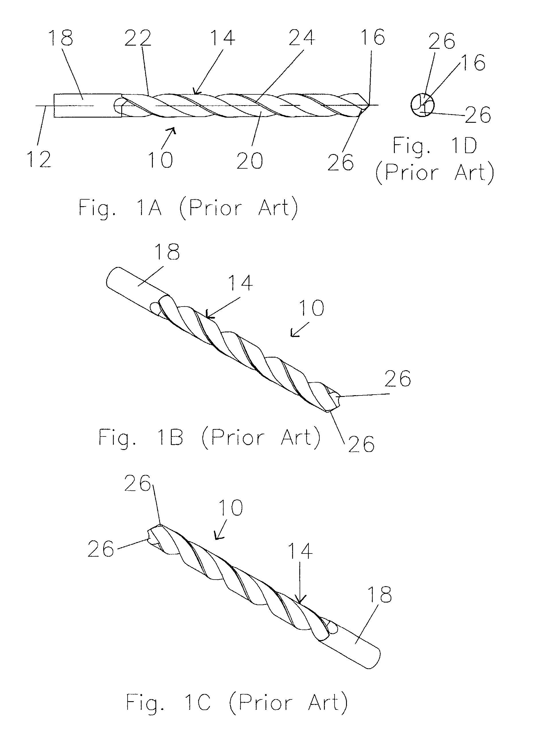
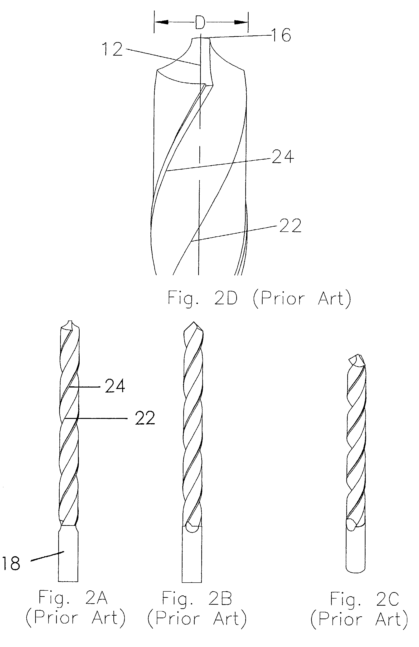
RELATED APPLICATIONS[0001]This application claims benefit of U.S. Provisional Patent Application No. 60 / 314,625, filed Aug. 23, 2001, and is a continuation-in-part of Application No. 10 / 007,005, filed Nov. 9, 2001, abandoned, which is a division of Application No. 09 / 174,887, filed Oct. 19, 1998, now U.S. Pat. No. 6,315,505, which is a division of Application No. 08 / 698,722, filed Aug. 15, 1996, now U.S. Pat. No. 5,823,720.TECHNICAL FIELD[0002]This invention provides in a conventional twist drill or “jobber bit” structural features that require less energy to drill a hole during a normal plunge operation and allow for lateral cutting movement during extraction from a drilled work piece.BACKGROUND OF THE INVENTION[0003]FIGS. 1A, 1B, and 1C are three side elevation views and FIG. 1D is a work end view of a conventional twist drill 10. The three side elevation views of FIGS. 1A, 1B, and 1C show twist drill 10 in different angular orientations of and about its longitudinal axis 12 to cl...

Claims


Application Information

Patent Timeline
IPC IPC(8): B23B51/02B23B27/04B23B51/00B23B51/04B23B51/10B23C5/08B23D61/02
CPCB23B51/009B23B51/02B23B2251/14Y10T408/9097Y10T408/906Y10T408/899B23B2251/44
Inventor MOORE, RICHARD A.
Owner BITMOORE AN OREGON GEN PARTNERSHIP
Learn More