
Wide swing, low power current mirror with high output impedance

a low power current mirror and high output impedance technology, applied in the field of electrical circuits, can solve the problems increasing the output impedance at the cost of reducing the output voltage swing (range), undesirable cost, die area, power consumption consequences, etc., and achieves high output impedance and high output voltage swing. , the effect of simple design

Active Publication Date: 2006-03-14
MICREL
View PDF6 Cites 6 Cited by
  • Summary
  • Abstract
  • Description
  • Claims
  • Application Information

AI Technical Summary

Benefits of technology

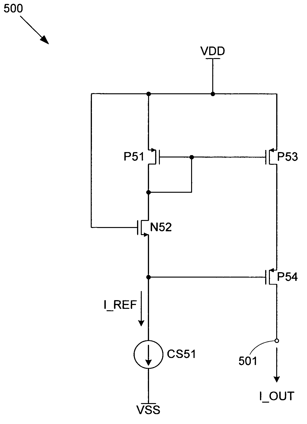
[0029]The invention includes a current mirror that provides high output impedance and high output voltage swing in a compact, simple design. The current mirror can be implemented using a single current source, thereby minimizing the power consumption of the current mirror.
[0034]In addition, this gate voltage provided to the gate of the output transistor allows the current mirror to have a relatively wide output voltage range. Specifically, the drain of the output transistor can swing from the first supply voltage all the way to twice its saturation voltage from the second supply voltage (assuming that all transistors are matched) before the output transistor falls out of saturation.

Problems solved by technology

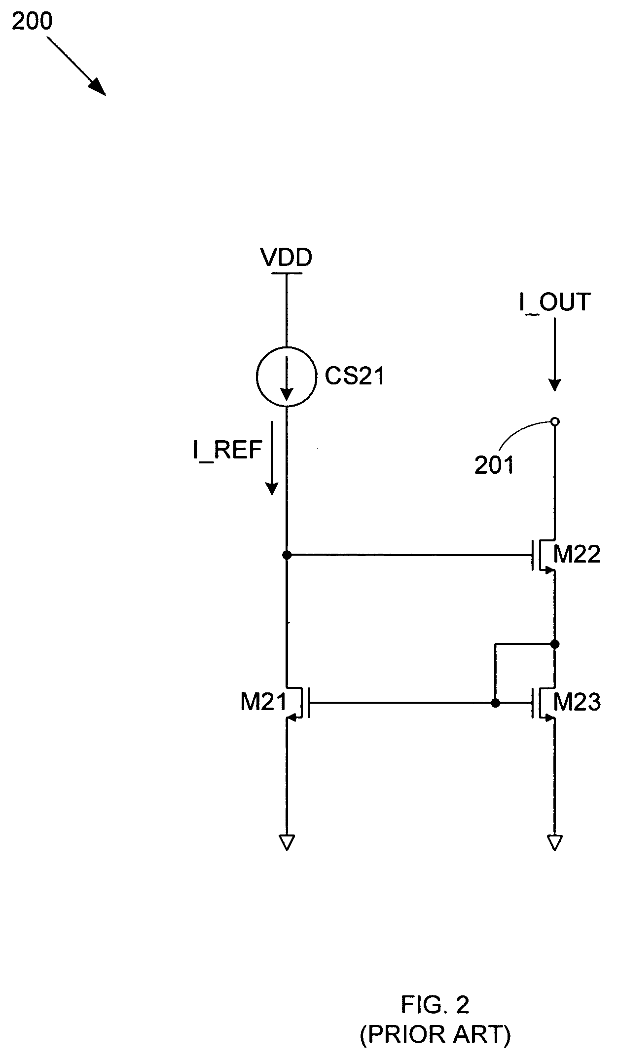
However, this increased output impedance comes at the cost of reduced output voltage swing (range).
However, the added complexity of current mirror 300 (i.e., the additional control branch formed by current source CS32 and transistors M33 and M34) can have undesirable cost, die area, and power consumption consequences.

Method used


Image

  • Wide swing, low power current mirror with high output impedance
  • Wide swing, low power current mirror with high output impedance
  • Wide swing, low power current mirror with high output impedance

Examples


Embodiment Construction

[0043]FIG. 4 shows a current mirror 400 in accordance with an embodiment of the invention. Current mirror 400 includes a current source CS41, an output terminal 401, a PMOS (p-type metal-oxide-semiconductor) transistor P41, and NMOS (n-type metal-oxide-semiconductor) transistors N42, N43, and N44.

[0044]Note that, for exemplary purposes, transistors P41, N42, N43, and N44 are all described as being matched transistors, and therefore share the same saturation voltages Vdsat and threshold voltages Vt. This matching of transistors allows current mirror 400 to provide a gain of unity (i.e., output current I_OUT is equal to reference current I_REF). However, according to various other embodiments of the invention, the transistors can be sized differently (i.e., can have different gate widths and / or lengths) to produce differing electrical characteristics so that any desired gain can be provided by current mirror 400.

[0045]Current source CS41, transistor P41, and transistor N42 are connect...


PUM


Abstract

A current mirror includes a serially connected diode-connected transistor of a first conductivity type, a saturated (fully-on) transistor of a second conductivity type, and a current source for providing a reference current. A gate voltage generated by the diode-connected transistor in response to the reference current is provided to the gate of a matching transistor. This causes the matching transistor to mirror the reference current. Meanwhile, an output transistor cascoded with the matching transistor is gate-coupled to the junction between the saturated transistor and the current source. This allows the output transistor to provide an output voltage swing from one supply voltage to two saturation voltage drops from the second supply voltage. Meanwhile, the cascode configuration gives the current mirror a high output impedance.

Description

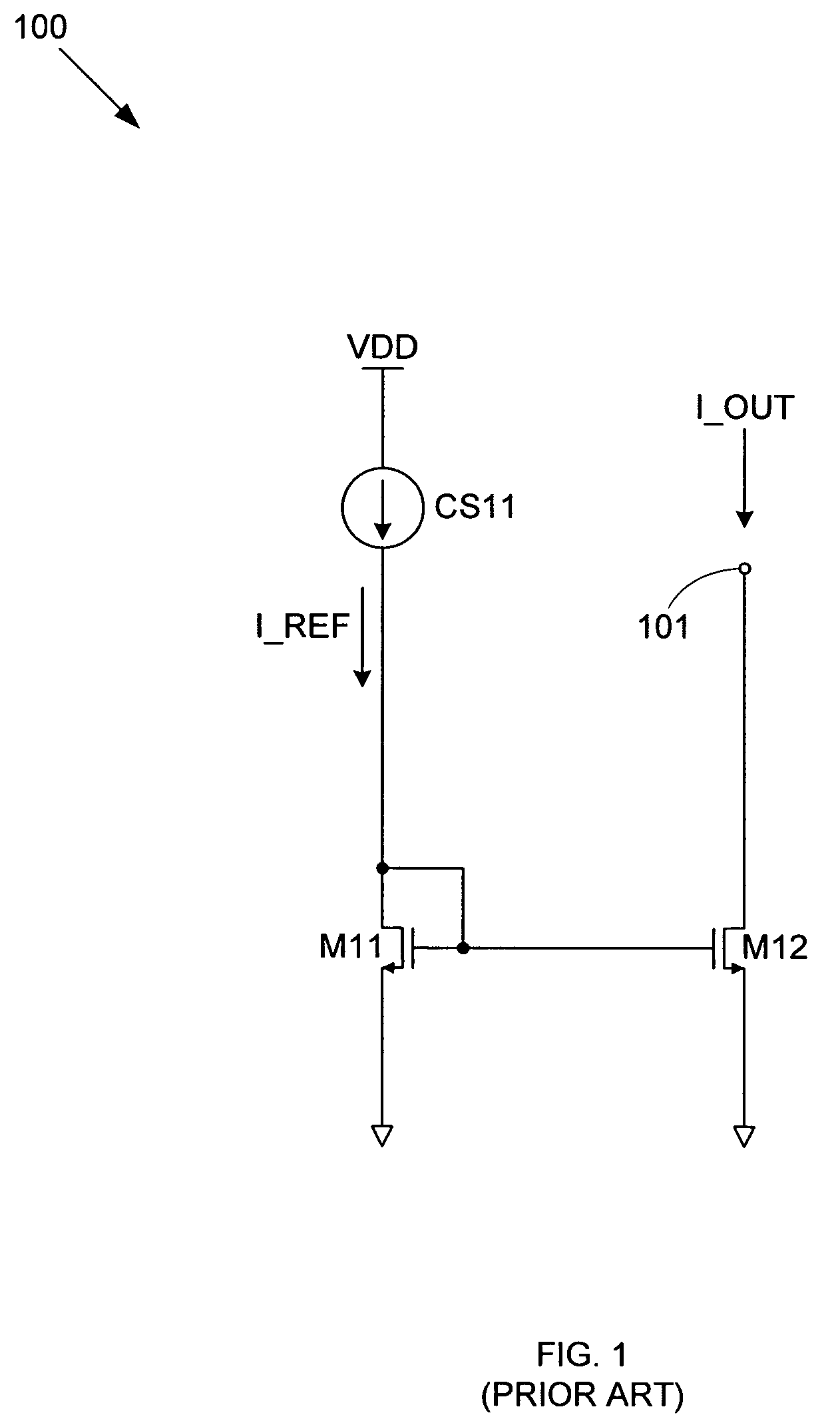
BACKGROUND OF THE INVENTION[0001]1. Field of the Invention[0002]The invention relates to electronic circuits, and in particular to a power-efficient current mirror with high output impedance and a wide output voltage range.[0003]2. Related Art[0004]A current mirror is used to duplicate a reference current in an integrated circuit (IC) for use in a different portion(s) of the IC. By providing this duplicate current, the current mirror can minimize the effects of the circuit operation on the reference current source.[0005]FIG. 1 shows a conventional current mirror 100 that includes a reference current source CS11, an output terminal 101, a reference transistor M11, and an output transistor M12. Current source CS11 and transistor M11 are connected in series between a supply voltage VDD and ground, while transistor M12 is connected between output terminal 101 and ground. The gates of transistors M11 and M12 are connected, and the gate of transistor M11 is connected to its drain (i.e., t...

Claims


Application Information

Patent Timeline
Patent Type & Authority Patents(United States)
IPC IPC(8): G05F3/16G05F3/26
CPCG05F3/262
Inventor MORAVEJI, FARHOOD
Owner MICREL
Learn More