
Integrated volume control and switch assembly

a technology of integrated volume control and switch assembly, which is applied in the direction of electric switches, resisitors with sliding contact, electric apparatus, etc., can solve the problems of not being able to independently adjust the angular position of the user's rotatable part, particularly troublesome, etc., and achieves cost-effective and simple design

Active Publication Date: 2006-03-14
SONION ROSKILDE
View PDF14 Cites 91 Cited by
  • Summary
  • Abstract
  • Description
  • Claims
  • Application Information

AI Technical Summary

Benefits of technology

"The present invention provides an integrated volume control and switch assembly for hearing aids and other small applications. The assembly has a simple design and is cost-efficient to manufacture. It includes a base plate, conductive switch legs, a resilient conductive member, and a resilient tactile member. The assembly can provide independently adjustable switch and feedback functions. The assembly is easy to manufacture and can be used in miniature versions. The invention allows for the separation of the switch and feedback functions, allowing for different angular positions for both functions. The assembly is easy to use, with a tactile feedback that indicates the change between switch states. The invention provides a solution for providing both tactile feedback and independent control of the switch in a single assembly."

Problems solved by technology

The combined switch and tactile feedback arrangement provided in PJ 88 has a number of disadvantages that are particularly troublesome with respect to further miniaturisation.
This means that the solutions are not suited for further miniaturisation, since a pure downscale of such potentiometers would include mechanical parts being too complicated to manufacture and handle in a cost efficient production process.
An additional problem with PJ 88 is that it is not possible to independently adjust an angular position of the user rotatable part where the switch function and the tactile feedback occur.

Method used


Image

  • Integrated volume control and switch assembly
  • Integrated volume control and switch assembly
  • Integrated volume control and switch assembly

Examples


Embodiment Construction

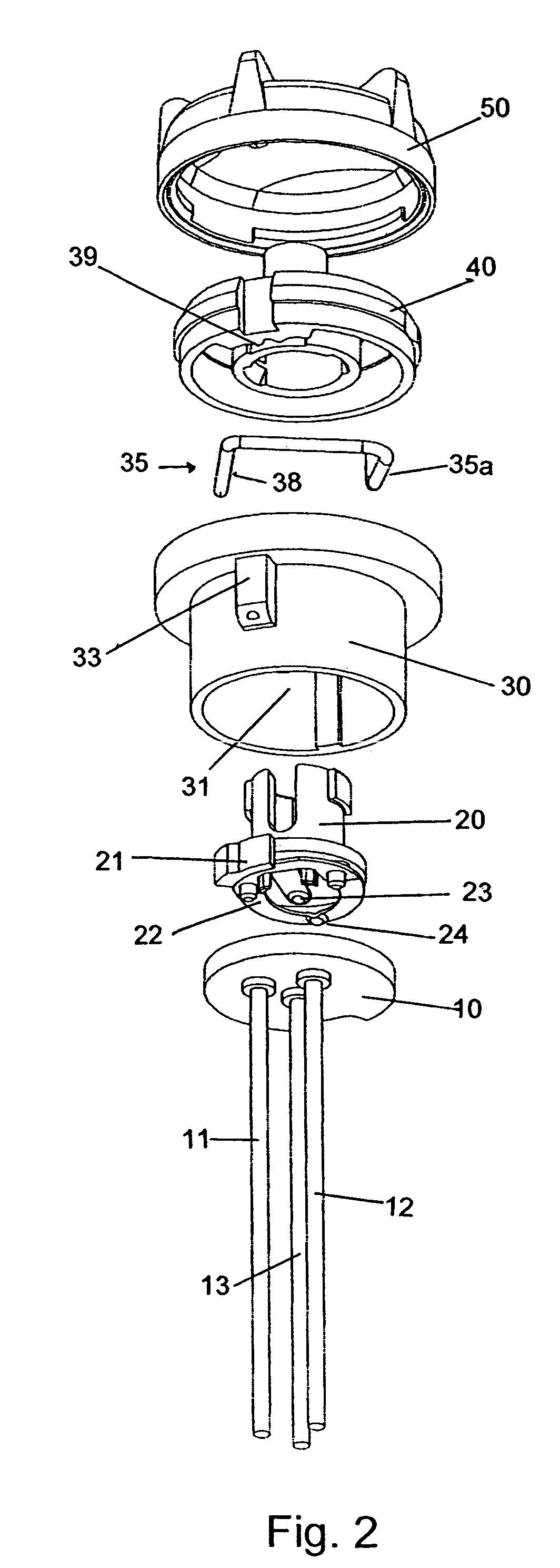
[0041]FIG. 1 shows a perspective view of selected parts of the assembly according to the invention showing from below a base plate 1 comprising first 2 and second 3 conductive switch legs. The first 2 and second 3 conductive switch legs penetrate the base plate 1 and form two terminals 4, 5, respectively, on an upper surface of the base plate 1. It is understood that even though denoted “legs” the first 2 and second 3 conductive switch legs may be formed differently than the long slim members or pins shown in the Figures. For example the switch legs 2,3 may be formed by conductive bumps adapted for soldering or they may be formed by pieces of Printed Circuit Boards (PCB), pieces of flexprint or flexible wires.

[0042]The base plate 1 further comprises three holes 6 for receiving third 11, fourth 12 and fifth 13 conductive legs mounted on substrate 10. These legs 11,12,13 form the termination of the 3-pin potentiometer part of the assembly. One of conductive legs 11 or 12 may be omitte...


PUM


Abstract

An integral volume control and switch assembly comprising a resilient conductive member serving for switching between a first and second switch state and a resilient tactile member serving for providing a user with a tactile feedback upon change of switch state. The resilient tactile member and the resilient conductive member are formed by separate members. Hereby the assembly can be further miniaturised without the resilient tactile member and the resilient conductive member being too small to handle in a manufacturing process. In addition, it is possible to adjust angular position of the rotatable member where switch function and tactile feedback occurs. Preferably the resilient tactile member and the resilient conductive member are spatially separated along a rotational axis of the rotatable member. The assembly according to the invention is suitable for hearing aids.

Description

FIELD OF THE INVENTION[0001]The present invention relates to an integrated volume control and switch assembly comprising a combined potentiometer and switch function. In particular, the assembly is suitable for use in hearing aids and portable communication devices.BACKGROUND OF THE INVENTION[0002]Known potentiometers may in addition to a variable resistance function have a built-in switch that provides the option of changing between first and second switch states via the potentiometer knob—typically in an extreme position of the potentiometer knob. The potentiometer may function as a volume control where the potentiometer knob upon turning in one direction decreases the volume, and finally turns off the signal and / or switches off power. Preferably, the user is provided with feedback indicating that the switch has reached an off state, e.g. light in a display or diode, a sound, a tactile mechanical resistance towards turning of the knob, or similar. In relation to volume controls fo...

Claims


Application Information

Patent Timeline
Patent Type & Authority Patents(United States)
IPC IPC(8): H01H19/58H01C10/36H01H3/02H04R25/00
CPCH01C10/36H04R25/00H01H3/0213H04R2225/61H04R25/603
Inventor MOLLER, NIELS THOR
Owner SONION ROSKILDE
Learn More