
Transfer member and manufacturing method thereof, and image forming apparatus using the same

a technology of transfer member and manufacturing method, which is applied in the direction of electrographic process, transportation and packaging, instruments, etc., can solve the problems of uneven and fine dispersion of carbon black responsible for controlling resistivity, uneven transfer, and decreased surface resistivity, and achieve excellent surface resistivity persistence and good transfer image.

Inactive Publication Date: 2006-03-07
FUJIFILM BUSINESS INNOVATION CORP
View PDF15 Cites 4 Cited by
  • Summary
  • Abstract
  • Description
  • Claims
  • Application Information

AI Technical Summary

Benefits of technology

[0015]Accordingly, it is an object of the present invention to provide a method for manufacturing a transfer member having desired resistivity characteristics that enables a good transfer image to be obtained while being excellent in persistence of the surface resistivity, and an image forming apparatus using the transfer member.

Problems solved by technology

As described above, while conductivity of the transfer member should be controlled to a desired level, there have been another problems that irregular transfer and decreased persistence of the surface resistivity were yet encountered even by attaining the desired resistivity.
This is believed to arise from the fact that carbon black responsible for controlling the resistivity is not uniformly and finely dispersed in the polyimide resin at a high concentration.

Method used


Image

  • Transfer member and manufacturing method thereof, and image forming apparatus using the same
  • Transfer member and manufacturing method thereof, and image forming apparatus using the same
  • Transfer member and manufacturing method thereof, and image forming apparatus using the same

Examples


example 1

[0074]Added in U-vanish S (trade name, manufactured by Ube Industries, Ltd., as a NMP solution of poly(amic acid) comprising 3,3′,4,4′-biphenyl tetracarboxylic acid dianhydride and paraphenylene diamine and having a solid content of 18 wt % after converting into polyimide) is 24.1 phr of carbon black (trade name: Special Black 4 manufactured by Degussa Co.; pH=3, volatile component 14 wt %). The solution is divided into two portions, and the divided solutions are allowed to collide with each other at a pressure of 200 MPa using Geanus PY (trade name, manufactured by Geanus Co.; the minimum cross sectional area of the collision portion: 0.032 mm2) having the same mechanism as the division and mixing mechanism as shown in FIG. 3. The solutions are mixed by passing through the path in FIG. 3 five times.

[0075]The mixed solution is coated on the outer surface of a die having a diameter of 305 mm by a dip method, and 70% of NMP as the solvent is removed by placing the die in a drying cham...

example 2

[0076]Added in U-vanish S manufactured by Ube Industries, Ltd. (as described above) is 23.2 phr of carbon black (trade name: Special Black 4 described above). The solution is divided into two portions, and the divided solutions are allowed to collide with each other at a pressure of 175 MPa using Geanus PY (as described above) having the same mechanism as the division and mixing mechanism as shown in FIG. 3. The solutions are mixed by passing through the path in FIG. 3 five times.

[0077]A polyimide belt with a thickness of 70 μm is manufactured by the same method as in Example 1 using the solution above.

example 3

[0078]Added in U-vanish S (as described above) is 22 phr of carbon black (trade name: Special Black 4 described above). The solution is divided into two portions, and the divided solutions are allowed to collide with each other at a pressure of 150 MPa using Geanus PY (as described above) having the same mechanism as the division and mixing mechanism as shown in FIG. 3. The solutions are mixed by passing through the path in FIG. 3 five times.

[0079]A polyimide belt with a thickness of 70 μm is manufactured by the same method as in Example 1 using the solution above.


PUM

PropertyMeasurementUnit
pressureaaaaaaaaaa
volume resistivityaaaaaaaaaa
particle diameteraaaaaaaaaa

Abstract

The present invention provides a transfer member containing a polyimide resin and carbon black. The carbon black has a pH value of no more than 5 and a volatile component of at least 3.5%, and the content of carbon black is 22 to 30 parts by weight relative to 100 parts by weight of the polyimide resin. The invention also provides a method for manufacturing a transfer member comprising the steps of: dividing a poly(amic acid) resin solution containing carbon black into plural portions, and mixing the divided solutions by allowed the solutions to collide with each other at a pressure of at least 150 MPa; and forming a transfer member containing the polyimide resin using the poly(amic acid) resin solution, which has the carbon black mixed therein. The invention further provides an image forming apparatus using the transfer member above.

Description

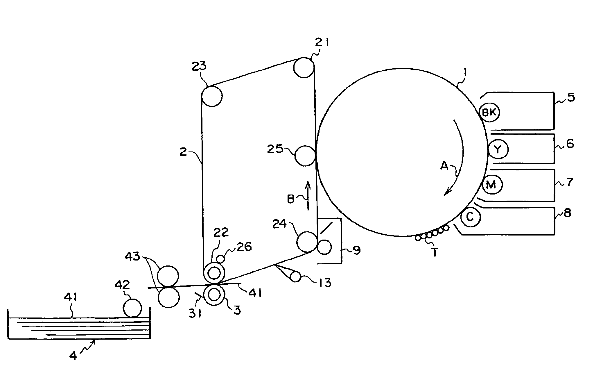
CROSS-REFERENCE TO RELATED APPLICATIONS[0001]This application claims benefit of and priority to Japanese Patent Application No. 2003-67875, filed on Mar. 13, 2003, which is incorporated herein by reference in its entirety for all purposes.BACKGROUND OF THE INVENTION[0002]1. Field of the Invention[0003]The present invention relates to a transfer member such as an intermediate transfer body used by an electrostatic copying system image forming apparatus such as a copying machine or printer.[0004]2. Description of the Related Art[0005]In an electrostatic copying system image forming apparatus, an image bearing body comprising a photoconductive photosensitive material is uniformly electrified, an electrostatic latent image is formed with a laser beam obtained by modulating image signals, and a visible toner image is obtained by developing the electrostatic latent image with an electrified toner.[0006]A so-called intermediate transfer system image forming apparatus is one of such image f...

Claims


Application Information

Patent Timeline
Patent Type & Authority Patents(United States)
IPC IPC(8): G03G7/00G03G13/16G03G15/16G03G15/00
CPCG03G15/1605G03G15/162
Inventor FUKUDA, SHIGERU
Owner FUJIFILM BUSINESS INNOVATION CORP
Learn More