Film deposition apparatus and film deposition method
a film deposition apparatus and film technology, applied in the field of film deposition apparatus and film deposition method, can solve the problem that the characteristics of arc heating method allowing film deposition at high rate cannot be fully taken advantage, and achieve the effect of stable shap
- Summary
- Abstract
- Description
- Claims
- Application Information
AI Technical Summary
Benefits of technology
Problems solved by technology
Method used
Image
Examples
example 1
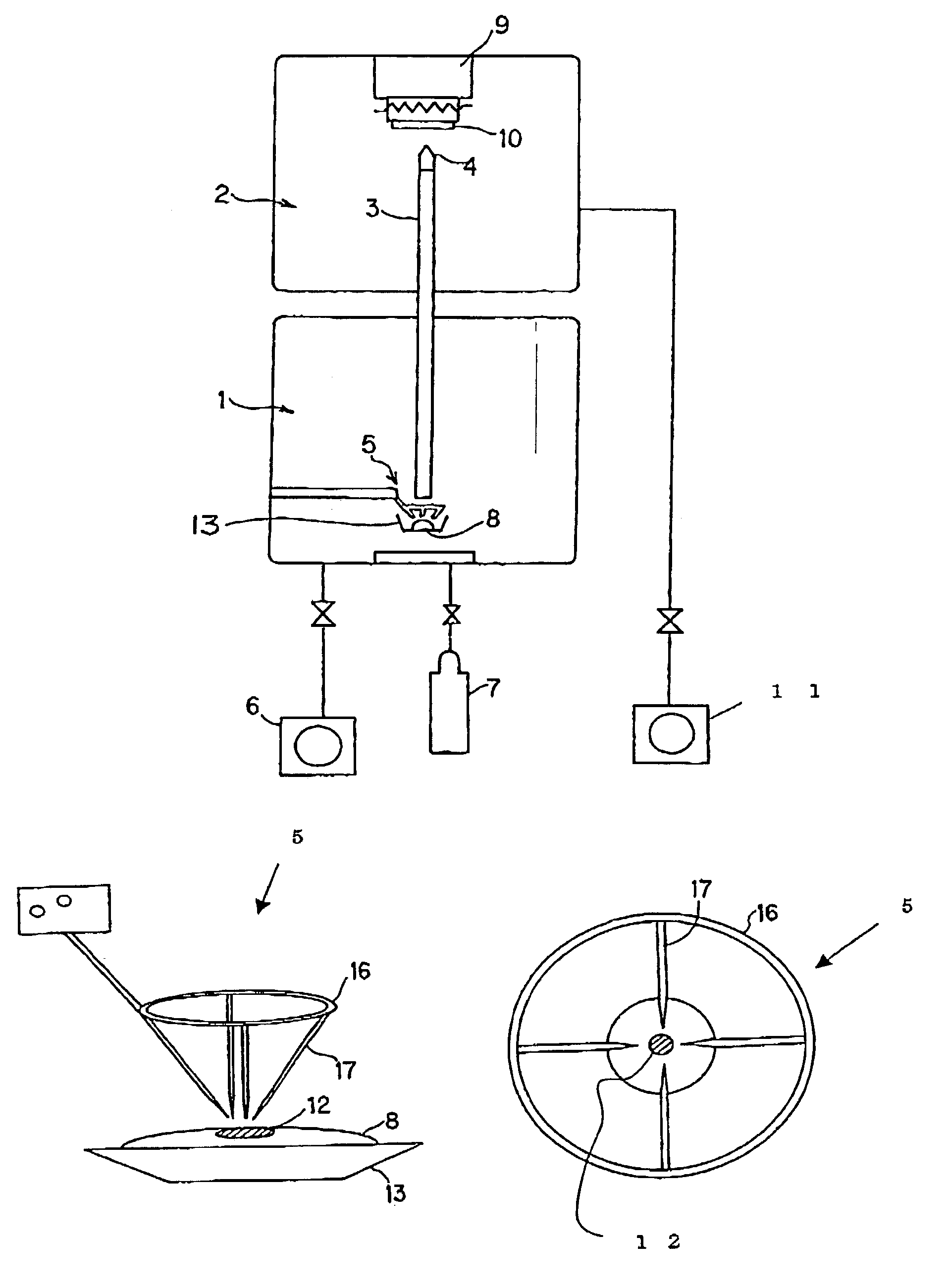
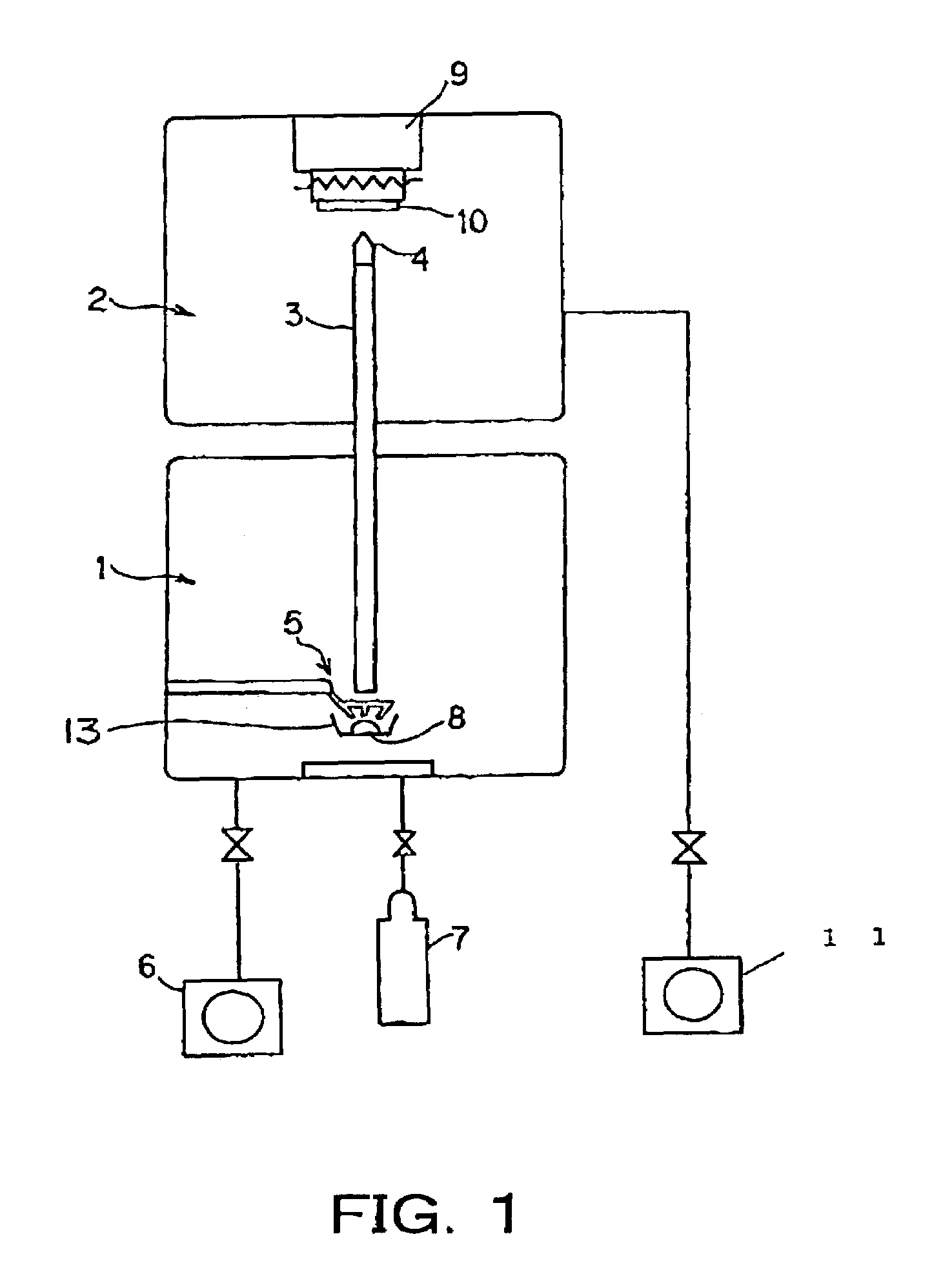
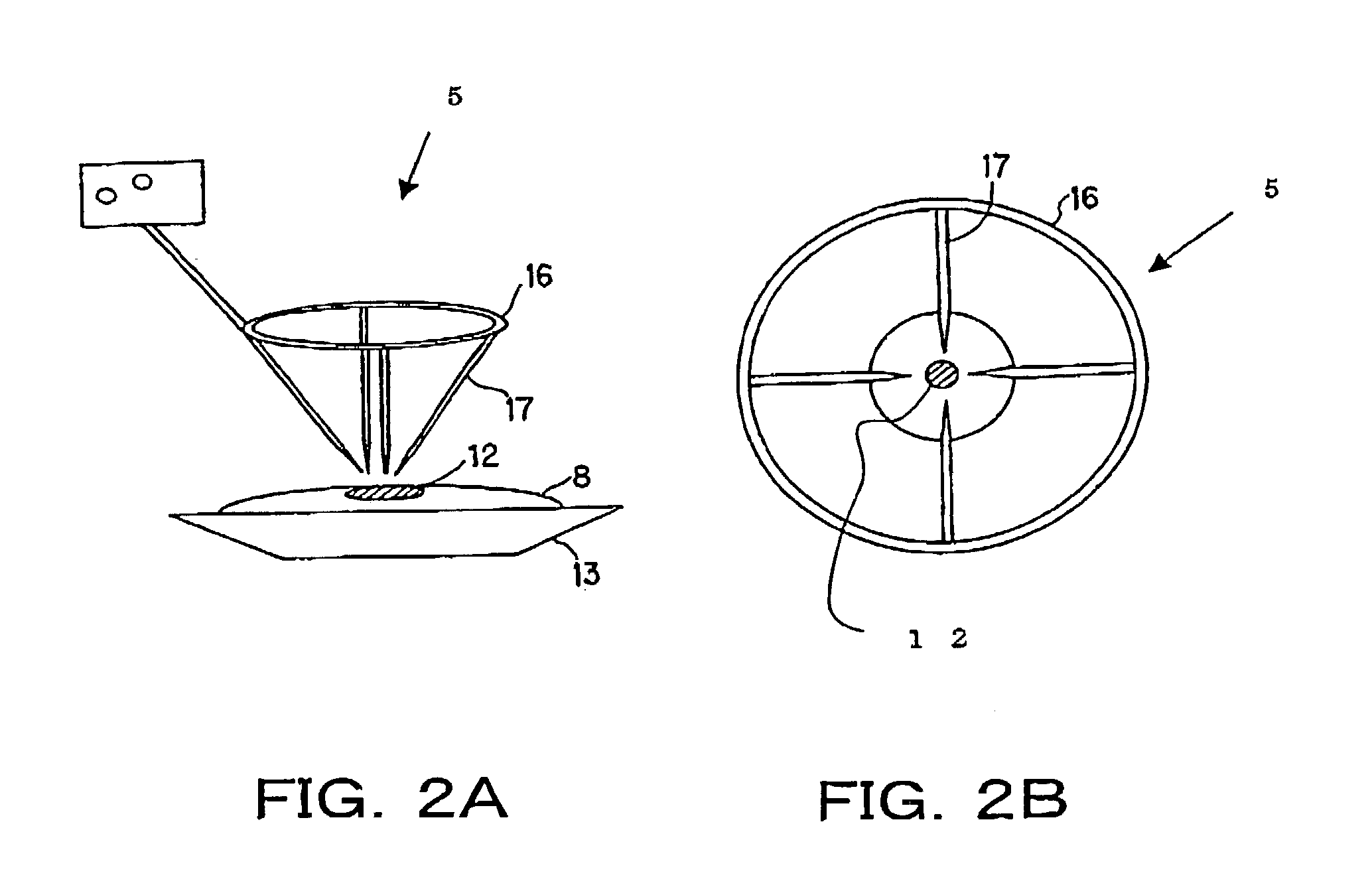
[0060]FIGS. 2A and 2B are both schematic diagrams showing the arc heating electrode 5 of the Example 1. The arc heating electrode 5 of Example 1 is configured by four sub electrodes (rod electrodes) 17. FIG. 2A is a perspective view, and FIG. 2B is a plan view. The general construction of the film deposition apparatus is equivalent to that schematically shown in FIG. 1.
[0061]As shown in FIGS. 2A and 2B, in this example, to use as the arc heating electrode (first electrode) 5 has a circular tungsten-made ring 16 with four 1 mm-diameter tungsten-made rods (sub electrodes) 17 fixed thereon. The tungsten-made rods 17 are so arranged that the tips thereof each form, lengthwise, an angle of approximately 45 degrees with respect to the vertical direction of the surface of the material 8. Further, the rods 17 are fixed on the circular tungsten-made ring 16 using screws so that the rod tips direct to the melting part 12 of the material 8. In this example, with such an arc heating electrode 5...
example 2
[0079]FIGS. 3A and 3B are both schematic diagrams showing the first electrode (arc discharge electrode) 5 of this example, more specifically, showing the first electrode 5 configured by eight sub electrodes 19. FIG. 3A is a perspective view, and FIG. 3B is a plan view. The general construction of the film deposition apparatus in its entirety is equivalent to the one schematically shown in FIG. 1.
[0080]As shown in FIGS. 3A and 3B, in this example, an octangle molybdenum-made jig 18 is provided with eight holes, at equal intervals, to allow 1 mm-diameter rod electrodes (sub electrodes) 19 to pass therethrough. As the rod electrodes 19, used are 1 mm-diameter eight tungsten-made rods 19 to which yttrium oxide (Y2O3) is doped. Here, the rod electrodes 19 are so arranged that the tips thereof each form, lengthwise, an angle of approximately 45 degrees with respect to the vertical direction of the surface of the material 8. Further, to have the rod tips direct to the melting part 12 of th...
example 3
[0098]FIGS. 4A to 4D are all schematic diagrams showing the arc heating electrode (first electrode) 5 of this example. In this example, three rod electrodes 21 are used as the sub-electrodes. FIG. 4A is a perspective view, FIG. 4B is a plan view, FIG. 4C is a perspective view of a rod electrode 21, and FIG. 4D is a plan view of the rod electrode 21. The general construction of the film deposition apparatus is equivalent to the one schematically shown in FIG. 1.
[0099]In this example, the sub-electrode configured by three carbon rods 21 is used to produce a mirror out of ultra fine A1 particles.
[0100]The carbon rod 21 is 1 mm in diameter. As shown in FIG. 4C, two of the three rod electrodes 21 are so fixed as to form an angle of 30 degrees with respect to the vertical direction of the surface of the material 8. The remaining one electrode is so fixed as to form an angle of 45 degrees with respect to the vertical direction of the surface of the material 8. The angles between the rods a...
PUM
| Property | Measurement | Unit |
|---|---|---|
| Shape | aaaaa | aaaaa |
Abstract
Description
Claims
Application Information
 - R&D
- Intellectual Property
- Life Sciences
- Materials
- Tech Scout
- Unparalleled Data Quality
- Higher Quality Content
- 60% Fewer Hallucinations
Browse by: Latest US Patents, China's latest patents, Technical Efficacy Thesaurus, Application Domain, Technology Topic, Popular Technical Reports.
© 2025 PatSnap. All rights reserved.Legal|Privacy policy|Modern Slavery Act Transparency Statement|Sitemap|About US| Contact US: help@patsnap.com


