
Method of making a multi-well test plate having adhesively secured transparent bottom panel

Inactive Publication Date: 2006-02-28
NALGE NUNC INTERNATIONAL
View PDF47 Cites 12 Cited by
  • Summary
  • Abstract
  • Description
  • Claims
  • Application Information

AI Technical Summary

Benefits of technology

[0007]As other equally important aspects of the invention, an adhesive as contemplated for the invention has various advantageous properties. These properties, singly or in various combinations, serve different functions and may be exhibited by a UV / V curable adhesive as mentioned above, or other heat curable or infrared curable adhesives or epoxies. For example, the adhesive has a viscosity that is preferably greater than about 8,000 cps to minimize flowing for more accurate adhesive placement. The adhesive is also thixotropic in nature in that it will not flow after application, for example, onto the upper surface of the glass panel. This has two beneficial results. First, the adhesive will not flow into an area of the glass panel that will become the bottom surface of a well so as to potentially contaminate the samples within the well. Also, the adhesive will not thin out after application and consequently decrease the adhesion between the glass panel and the upper frame portion.
[0008]The adhesive is also preferably transparent and this aspect has been found advantageous for the reason that it will not interfere with detection made from the bottom of the plate, due to specific wavelength absorbance or reflection. Curability by UV and visual light is advantageous because complete cure and nontoxicity is ensured by UV exposure followed by additional exposure to visual light. A one component adhesive as described herein eliminates the need for mixing and its associated problems such as variability in time between mixing and application. The adhesive cures to form a flexible joint to prevent stress cracking during cure and later during use of product at various temperatures. The adhesive is stable during and after ethylene oxide and gamma sterilization. The adhesive is nontoxic and is USP Class VI.

Problems solved by technology

The UV / V light curing process does not modify the glass bottom panel of the preferred embodiment in a manner that adversely affects performance.
Also, the adhesive will not thin out after application and consequently decrease the adhesion between the glass panel and the upper frame portion.
Such off-gassing could result in sample contamination.

Method used


Image

  • Method of making a multi-well test plate having adhesively secured transparent bottom panel
  • Method of making a multi-well test plate having adhesively secured transparent bottom panel
  • Method of making a multi-well test plate having adhesively secured transparent bottom panel

Examples


Embodiment Construction

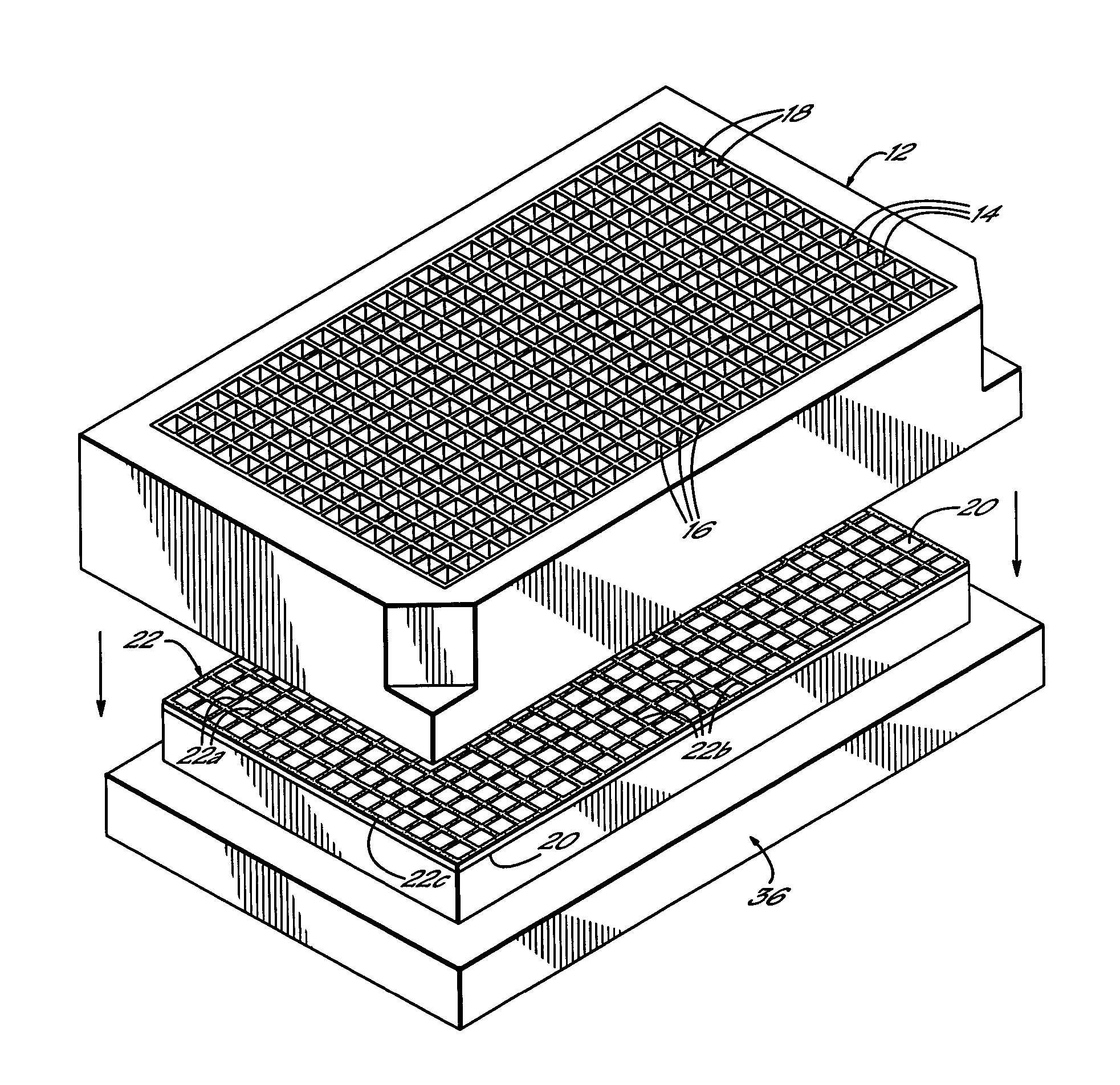
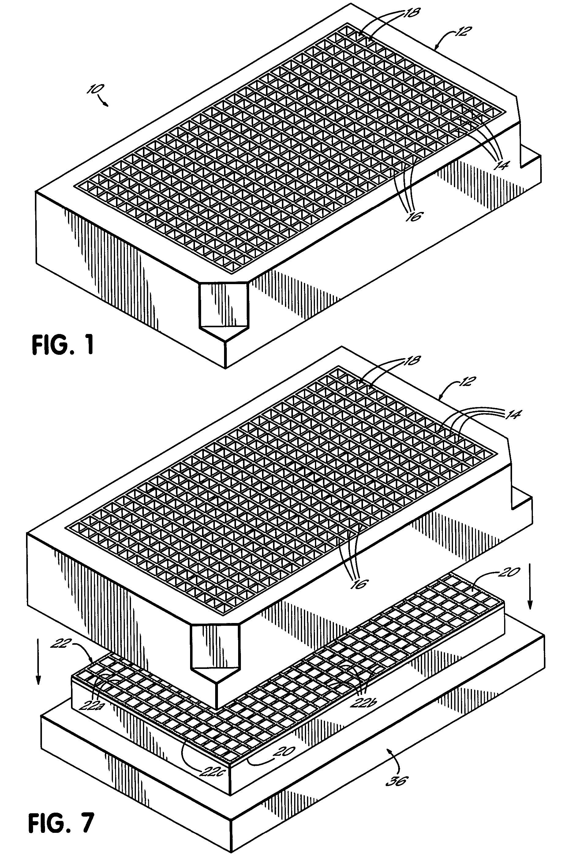
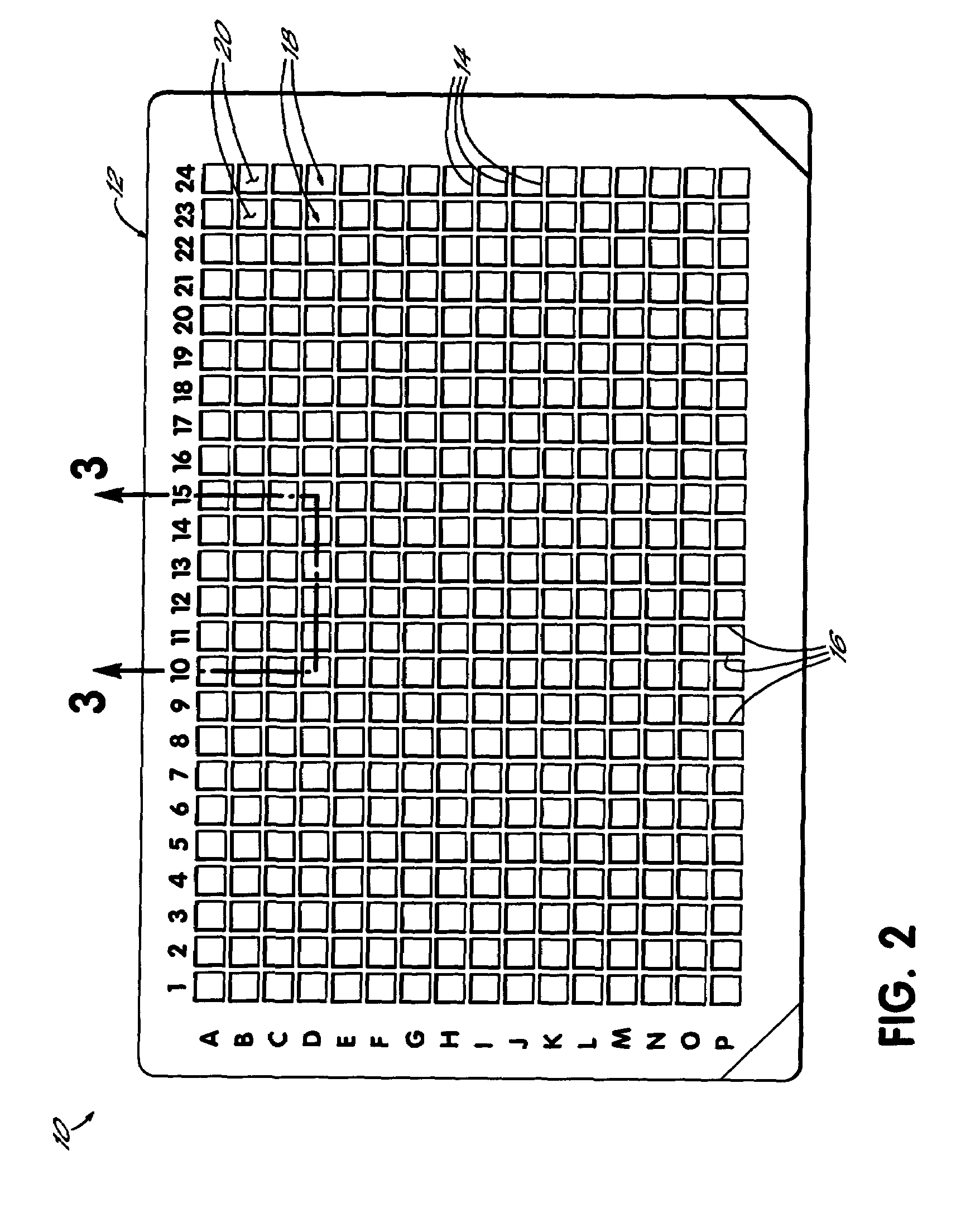
[0018]Referring first to FIGS. 1–3, a multi-well test plate 10 constructed in accordance with one preferred embodiment of the invention generally comprises an upper frame portion 12 having a plurality of intersecting walls 14, 16. Upper frame portion 12 is preferably formed from a polymer, such as polystrene, and is preferably opaque. Depending on the intended use of test plate 10, upper frame portion 12 can be transparent, black or white in color. White has advantageous light reflective properties, while black has advantageous light absorptive properties. Walls 14, 16 form independent wells 18 for receiving liquid assay samples. The specific embodiment shown and described herein includes 384 square wells 18, however, it should be understood that a greater or fewer number of wells may be used in a multi-well test plate constructed in accordance with the inventive concepts. Also, the square wells shown and described herein are also for illustrative purposes and may be substituted wit...


PUM

PropertyMeasurementUnit
Poweraaaaaaaaaa
Poweraaaaaaaaaa
Viscosityaaaaaaaaaa

Abstract

A method of making a multi-well test plate including an upper frame portion and a glass panel secured to a lower side of the upper frame portion with a layer of light-curable adhesive. The upper frame portion includes a plurality of walls defining adjacent wells for receiving assay samples. The adhesive has various properties, such as high viscosity, thixotropicity, transparency, water insolubility, non-autofluorescence, and non-toxicity, as well as others that are advantageous when constructing and using the multi-well test plate. The adhesive is preferably applied by a screen transfer process that takes advantage of the adhesive properties.

Description

CROSS-REFERENCE TO RELATED APPLICATIONS[0001]This application is a divisional of application Ser. No. 09 / 427,235, filed Oct. 26, 1999, now abandoned, the disclosure of which is hereby fully incorporated by reference herein.FIELD OF THE INVENTION[0002]The present invention generally relates to multi-well test plates or so-called micro-plates for assaying liquid samples and, more particularly, to multi-well test plates having glass bottoms secured to a framework of wells for containing the liquid samples.BACKGROUND OF THE INVENTION[0003]Multi-well test plates are well known in scientific areas, such as biotechnology, for allowing the detection and measurement of substances present in translucent liquid samples. Generally, this is accomplished by measuring the light absorbence characteristics of the sample through one or more spectroscopy procedures. Typically, a framework of test wells is open at the top for receiving the liquid samples and is closed with a transparent bottom, formed ...

Claims


Application Information

Patent Timeline
IPC IPC(8): C12M1/00B01L3/00B32B37/14B32B37/16
CPCB01L3/5085B32B37/146B32B37/1292B01L2200/12
Inventor KHAN, ABDUL WAHIDSCHOLZ, WENDY KAYTRACY, ERIKA LYNNKELLY, MARGARET MARIA
Owner NALGE NUNC INTERNATIONAL
Learn More