
Flow control of photo-polymerizable resin

a technology of photopolymerizable resin and flow control, which is applied in the field of methods and systems to control the flow of photopolymerizable resin, can solve the problems of adhesive application, spot curing, and adhesive residues that are not spot cured, and are wasteful and messy

Active Publication Date: 2006-02-21
CAPLIPER LIFE SCI INC
View PDF10 Cites 108 Cited by
  • Summary
  • Abstract
  • Description
  • Claims
  • Application Information

AI Technical Summary

Benefits of technology

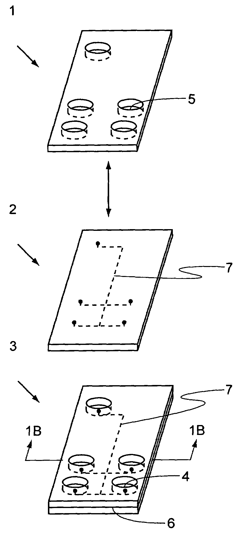
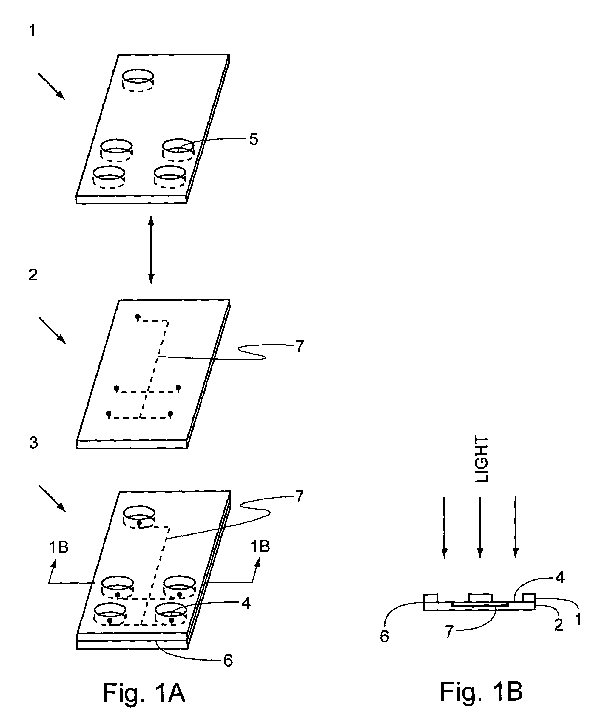
[0008]Embodiments of the present invention provide methods and systems for controling the flow and precisely situating photo-polymerizable resins on the surface of a substrate. Methods in accordance with the invention can be used to bind patterned polymers onto a substrate, to bond microfluidic chips to reagent well caddies without clogging microchannels, and to bond optic fibers to articles of manufacture without obscuring the fiber end with adhesive.
[0012]A photo-polymerizable resin is a fluid that can solidify on exposure to light. Typically, resins in the methods of the invention flow as a liquid, seeking the lowest level in the structure containing them. For example, resins confined within a series of barriers on a horizontal substrate will flow to form a smooth level surface. Resins in accordance with the invention can flow by capillary action in any direction that the forces of surface tension and surface adhesion will carry them. Resin flow, in embodiments of this invention, can be precisely controlled by polymerized resin barriers formed at interfaces between dark and light surfaces.
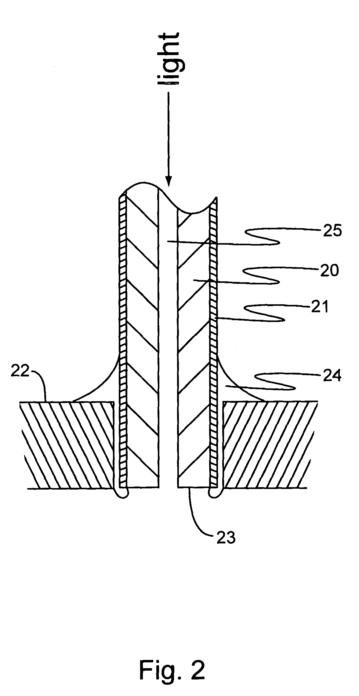
[0015]The mask in a system in accordance with the invention can be an object that casts a useful shadow pattern of resin flow restriction onto a substrate. A microfluidic reagent well caddie can be a mask that allows illumination of reagent well bottom surfaces to prevent flow of resin into microchannel inlet ports. A mask can be in close association with the substrate and have an affinity for the resin so that the resin can flow between the mask and the substrate by capillary action to bond the mask to the substrate. A semiconductor chip can function as a mask that allows illumination around the edges to prevent flow of adhesive resin beyond the base of the chip. An opaque cladding on an optic fiber or capillary tube can function as a mask that allows illumination of the ends so the sides can be bound to equipment without adhesive blocking light or fluid flow at the tip. The mask of the system can be provided as a reflective / refractive surface having a pattern of refraction critical angle perturbations (such as regions of higher or lower critical angles) that can reflect light away from adhesive flow regions and / or refract light onto resin exclusion regions; those skilled in the art can appreciate that a reflective / refractive mask can reflect light onto resin exclusion regions and / or refract light away from adhesive flow regions.
[0016]The substrate of a system in accordance with the invention can be an object with a surface where photo-polymerizable resins of the invention will flow. For example, the substrate can be the top surface of a microfluidic chip where reagent wells are precisely bonded or the bottom surface where capillary sip tubes are precisely bonded. To bond the reagent wells to the microfluidic chip, the well caddie can be closely positioned under the horizontal chip surface and flow of resin into the wells can be prevented with illumination from below. The illuminated substrate can be the end surfaces of clad capillary tubes or optic fibers, while the dark regions of the substrate can be the closely associated surfaces of the receiving article of manufacture.

Problems solved by technology

Still, adhesives have tended to be applied and cured in an imprecise and wasteful manner.
These spot curing techniques are not intended to prevent adhesives from migrating onto restricted surfaces.
Adhesive applied, but not spot cured, remain as a wasteful messy residue.

Method used


Image

  • Flow control of photo-polymerizable resin
  • Flow control of photo-polymerizable resin
  • Flow control of photo-polymerizable resin

Examples


Embodiment Construction

[0024]Embodiments of the present invention provide methods to control the flow of photo-polymerizable resin on a substrate. These methods can include the steps of precisely illuminating resin exclusion regions of a substrate and flowing photo-polymerizable resin onto the substrate, whereby polymerized resin flow barriers are created at the periphery of illuminated regions. The systems of the invention include a source of light, a mask, a substrate and a photo-polymerizable resin.

[0025]In an aspect of the invention, a substrate is illuminated through a mask to form a precise pattern of illuminated regions and dark regions. Photo-polymerizable resin can be applied to fill dark regions of the substrate and to flow to the edges of illuminated resin exclusion regions. Polymerization is initiated as the leading edge of the flowing resin is exposed to light at the interface between the resin exclusion and dark regions. The leading edge is a viscous polymerized barrier that substantially pr...


PUM

PropertyMeasurementUnit
transparentaaaaaaaaaa
reflectionaaaaaaaaaa
refractionaaaaaaaaaa

Abstract

This invention provides methods and systems, e.g., to control the flow of photo-polymerizable resins. In the method, e.g., flow of a photo-polymerizable resin is restricted from illuminated resin exclusion regions on a substrate surface by precisely situated flow barriers. A system to control photo-polymerizable resin flow includes, e.g., a light source, a mask and a substrate.

Description

CROSS-REFERENCE TO RELATED APPLICATIONS[0001]This application claims the benefit of U.S. Provisional Patent Application No. 60 / 407,407, filed Aug. 30, 2002, which is incorporated herein by reference in its entirety for all purposes.FIELD OF THE INVENTION[0002]This invention is in the field of methods and systems to control the flow of photo-polymerizable resin. More specifically, the invention relates to methods and systems for limiting the flow of photo-polymerizable resin to precisely situate the resin in desired locations.BACKGROUND OF THE INVENTION[0003]Adhesives are generally applied as a liquid that eventually solidifies and binds to a surface. From ancient times, water based adhesives (glues) were extracted from plant or animal sources. These glues usually bound to surfaces, or bound two surfaces together, as they slowly dried. With the advent of plastics and other modern polymers, adhesives were created that solidify and bind surfaces through chain elongation chemistries (po...

Claims


Application Information

Patent Timeline
Patent Type & Authority Patents(United States)
IPC IPC(8): H01L21/31
CPCB01L3/502707B29C65/548B29C66/1122C03C17/32C03C17/3405C03C23/0025H01L21/6715B29C65/4845B29C66/522B29C66/53465B29C65/00B29C66/5224B29C65/4855B01L2200/0689B01L2300/0816B01L2300/0887B29C65/14B29C65/1406B29C65/1412B29C65/16B29C65/546C03C2218/328B01L2200/027B29C65/4835B29C66/112B29C66/114
Inventor BROWN, TIMOTHY B.KURTH, RICHARD
Owner CAPLIPER LIFE SCI INC
Learn More