Piezoelectric laminate motion sensing apparatus and method

Inactive Publication Date: 2006-02-14
NAT TAIWAN UNIV
View PDF9 Cites 3 Cited by
  • Summary
  • Abstract
  • Description
  • Claims
  • Application Information

AI Technical Summary

Benefits of technology

[0006]It is an objective of the present invention to provide a miniature distributed sensing system that is applicable for many different structures, without the need for significant redesign. The invention comprises an effectively one-dimensional motion sensing system utilizing piezoelectric laminates with predetermined surface electrode patterns disposed thereon. A frequency selector passes motion waves of predetermined frequencies and an electrical circuit processes the electrical signals and transmits them to an activating device for activation in response to the electrical signals. In particular, the frequency selector is a low frequency bandpass filter for free-fall acceleration wave frequencies. By directing appropriate action, the present invention increases the applicability of the device upon which it is mounted (e.g., for military or other hostile environment use), decreases the possibility of damage, and lengthens its useful life.

Problems solved by technology

However, actuator / observer spillover due to residual (uncontrolled) vibration modes in conventional systems lead to instabilities in closed-loop control systems.
In one prior art instance, a modal-filtering process generated signals from an array of discrete point sensors simultaneously and then fed the signals into a control loop circuit, but the large number of signals and subsequent amount of signal processing required resulted in significant phase delays in the control loop circuit, thereby rendering the system unreliable at best and inoperable at worst.
However, in practice, conventional point sensors are clearly affected by the characteristics of their own structure when making a motion detection and thus they are limited by an effective use bandwidth (i.e., within which there is no self-effect).
Thus distributed sensing systems suffered from lack of general applicability.
However, conventional piezoelectric materials are typically crystalline or polycrystalline and therefore brittle and not easily conformable.

Method used


Image

  • Piezoelectric laminate motion sensing apparatus and method
  • Piezoelectric laminate motion sensing apparatus and method
  • Piezoelectric laminate motion sensing apparatus and method

Examples


Embodiment Construction

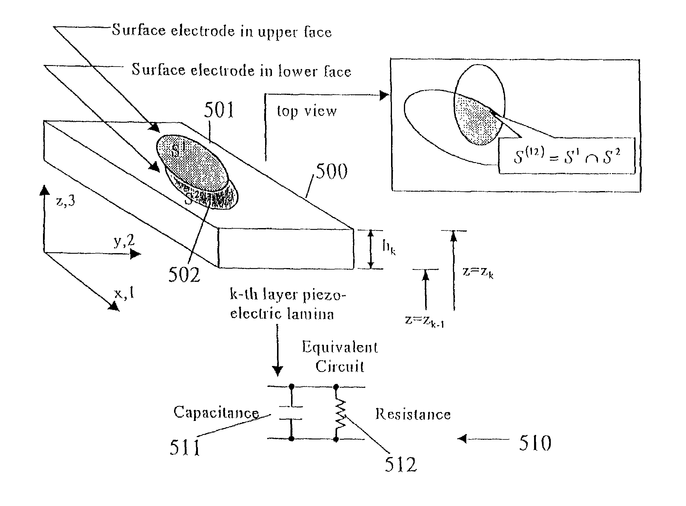
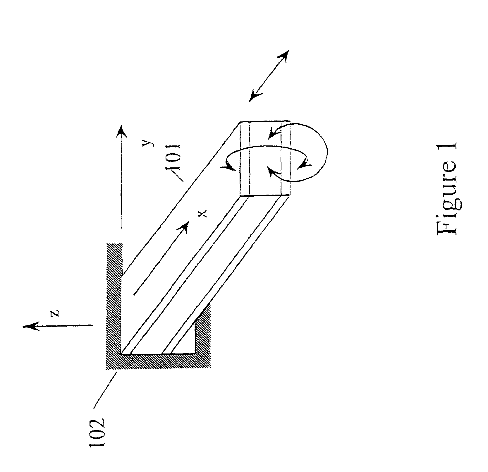
[0026]The preferred embodiment of the present invention is a motion sensor / actuator utilizing conformable piezoelectric laminate sensor structures having discrete and distributed surface electrode arrays. In one preferred embodiment, extremely low frequency motions or vibrations are sensed and the boundary conditions of the structure itself and other special characteristics of the structure, such as its self-damping function act to avoid phase delays in the control system and provide compensation for the entire system. The present invention utilizes a normal mode expansion distributed modal sensors design which, together with appropriate boundary conditions, produce a characteristic polynomial wave transmission spatial bandpass filter. The frequency response functions of the distributed sensors provide an adjustment capability for increasing the bandwidth of the measurement and / or increasing the frequency selection, thereby providing a system suitable for detection and actuation of ...


PUM


Abstract

A motion sensing system utilizing piezoelectric laminates with predetermined surface electrode patterns disposed thereon utilizes a frequency selector to pass motion waves of predetermined frequencies and an electrical circuit for processing the electrical signals for transmission to an activating device for appropriate activation. In particular, the frequency selector is a low frequency bandpass filter for free-fall acceleration wave frequencies. By directing appropriate action, the present invention increases the applicability of the device upon which it is mounted (e.g., for military or other hostile environment use), decreases the possibility of damage, and lengthens its useful life.

Description

FIELD OF THE INVENTION[0001]This invention relates generally to motion sensing devices and more particularly to a conformable piezoelectric laminate sensing structure utilizing a distribute electrode pattern for sensing free-fall motion waves.BACKGROUND OF THE INVENTION[0002]A point sensor / actuator (accelerometer or transducer) utilizing the piezoelectric effect reacts to or induces force, displacement, or acceleration at a point in a structure embodying the sensor / actuator. No a priori knowledge about the structure is needed to achieve the desired sensing or actuating. Discrete point sensors / actuators to detect and control the vibrations of flexible structures such as robot arms, satellite antennas and the like have been in existence for over thirty years. However, actuator / observer spillover due to residual (uncontrolled) vibration modes in conventional systems lead to instabilities in closed-loop control systems. The independent modal-space control method utilizing pre-filtering ...

Claims


Application Information

Patent Timeline
IPC IPC(8): H01L41/08H01L41/047H01L41/113
CPCH01L41/1132H01L41/047H10N30/87H10N30/302
Inventor LEE, CHIH-KUNGHSU, YU-HSIANGHUANG, LONG-SUNHSIEH, DER-CHANG
Owner NAT TAIWAN UNIV
Why Eureka
Try Eureka