Virtual stop station

Active Publication Date: 2019-03-19
R P GATTA
View PDF5 Cites 8 Cited by
  • Summary
  • Abstract
  • Description
  • Claims
  • Application Information

AI Technical Summary

Benefits of technology

The present invention provides a way to add a stop station to an assembly line without needing to modify it or taking up additional space. This can improve manufacturing quality, increase productivity, and reduce costs. Additionally, it can help reduce potential down time or cycle time. The invention allows for the placement of a virtual stop station anywhere within the assembly line, without worrying about variations in the workpiece's position relative to subsequent processing equipment. The invention is not limited to current state of the art, and can be adapted to meet future developments in material handling in manufacturing systems.

Problems solved by technology

A huge limitation of such systems is that the “line” moves at a certain speed and, as such, all the goods on the line are moving at the same pace.
This becomes a problem when a particular assembly subprocess is more complex or time consuming than would be otherwise dictated by the pace of the line.
There is a cost associated with inserting these new conveyor sections into the moving assembly line.
A problem with this method is that the encoder is coupled to the assembly line conveyor drive which is often a great distance away from the Robotic Automation station.
Because the assembly line conveyors in such a configuration may be chain driven conveyors, the backlash in the chain combined with chain wear elongation causes the feedback positioning to be very inaccurate.
Further, when the assembly lines stops and starts which is a normal occurrence in the automotive assembly process, the chain backlash may shift causing even greater inaccuracy during acceleration and decelerations of the assembly line.
Also, there is a cost associated with running electrical cable the long distance from the encoder to the robot controller(s).

Method used


Image

  • Virtual stop station
  • Virtual stop station
  • Virtual stop station

Examples


Embodiment Construction

[0030]For purposes of the present invention, the terms “a” and “an” herein do not denote a limitation of quantity, but rather denote the presence of at least one of the referenced items.

[0031]For purposes of the present invention, the term “anticipate” or “anticipated” should not be construed as a legal term of art in the context of prior invention or disclosure, but rather more generally in the colloquial or common usage sense as meaning expected, or given advance thought or future treatment.

[0032]For purposes of the present invention, the term “encoder” should be interpreted broadly as any mean for converting information from one format or code to another, and may be a device, circuit, transducer, software program, algorithm or person that converts such information for the purposes of standardization, speed, secrecy, security or compressions. As used herein may be a rotary encoder converts rotary position to an analog (e.g., analog quadrature) or digital (e.g., digital quadrature,...


PUM


Abstract

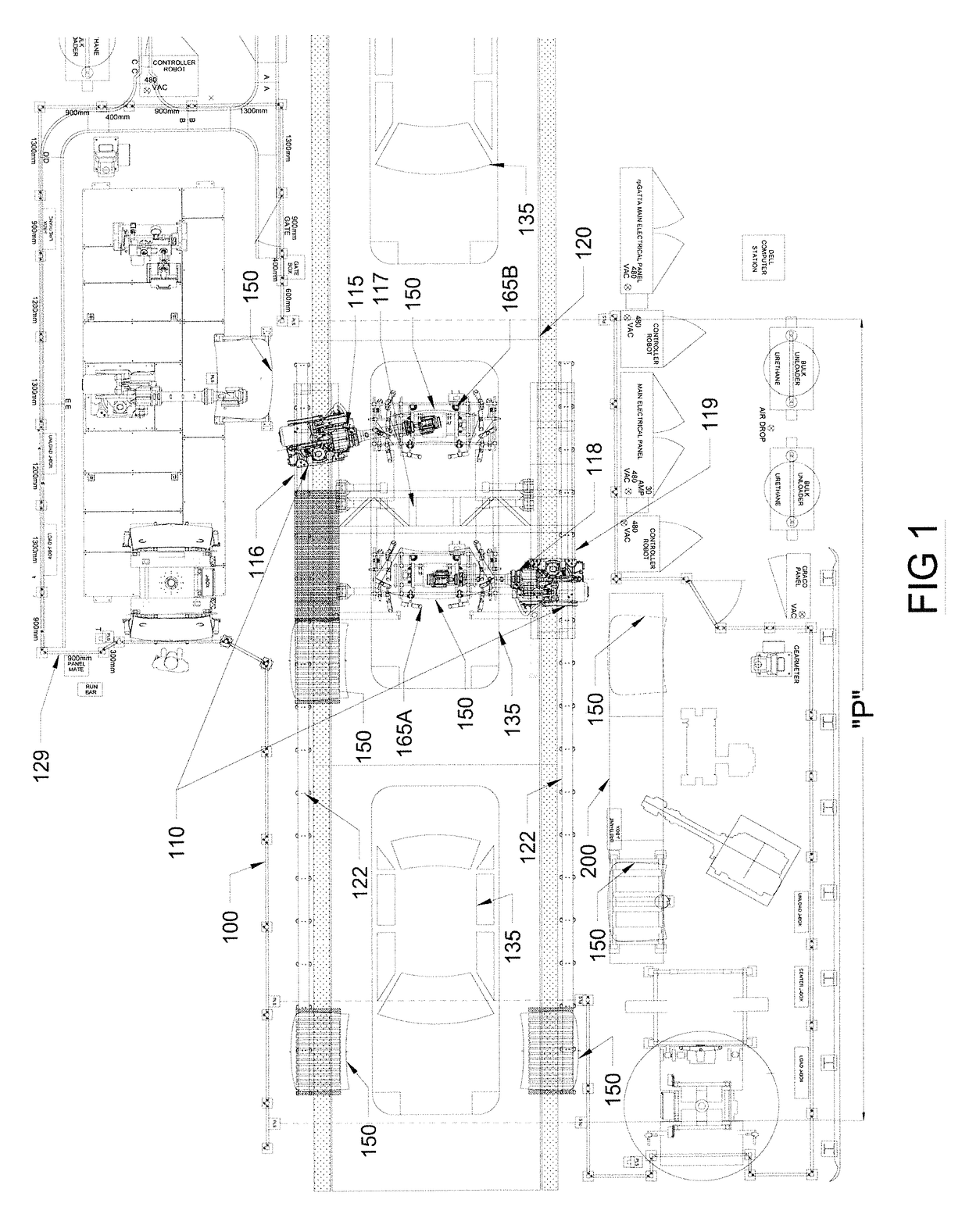
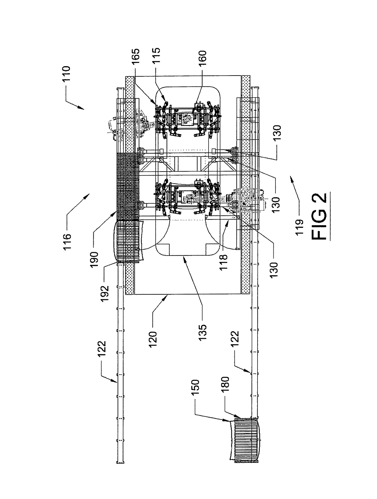
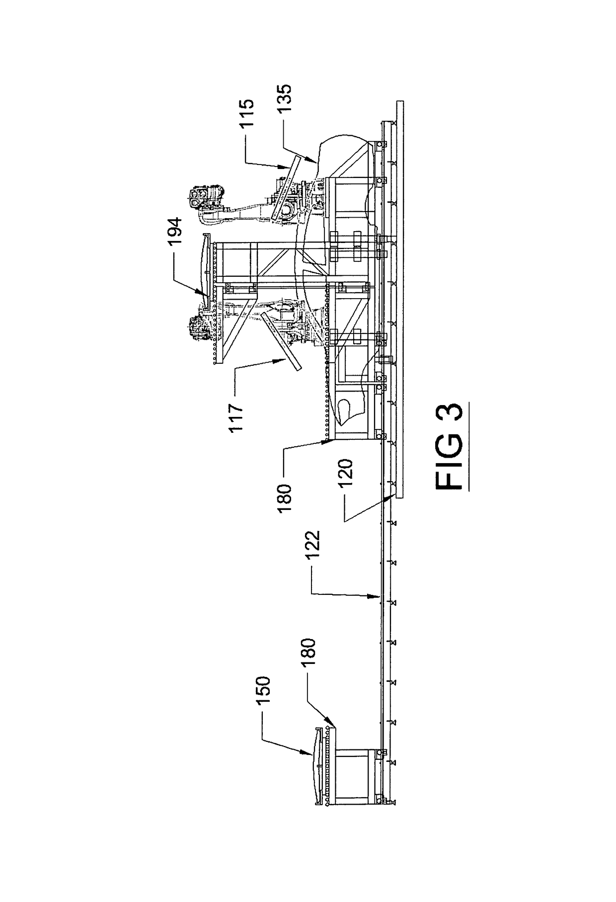
A virtual stop station is provided having a carriage straddling an assembly line operation. This provides an independently moving platform upon which one or more manufacturing robots are affixed. The carriage is coordinated with and tracked to the linear motion of the assembly line. A vision guidance system centers the workpiece, and lifting arms mounted on the moving carriage will locate the workpiece and lift the workpiece up off of the conveyor, while being coordinated with it. The workpiece and robots thus are now fixtured to the same frame, thus eliminating movement relative to one another creating a virtual stop station. Once subassembly is complete, the coordinated robotic gantry will disengage from the conveyor and return home. The instant abstract is neither intended to define the invention disclosed in this specification nor intended to limit the scope of the invention in any way.

Description

RELATED APPLICATIONS[0001]There are no previously filed, nor currently any co-pending applications, anywhere in the world.BACKGROUND OF THE INVENTION1. Field of the Invention[0002]The present invention relates generally to manufacturing assembly lines and, more particularly, to a system and method for increasing the adaptability of an assembly line for the progressive assembly of manufactured goods.2. Description of the Related Art[0003]An assembly line is a manufacturing process in which parts are added as a semi-finished assembly or workpiece moves from work station to work station. Since its innovation in 1901 by the Olds Motor Vehicle Company, and its improvements by Henry Ford in 1913, assembly lines have become the common method of assembling complex items such as automobiles and other transportation equipment, household appliances and electronic goods.[0004]The innovations of Henry Ford continue to exist today in automobile production. By mechanically moving the parts to the ...

Claims


Application Information

Patent Timeline
IPC IPC(8): B62D65/18B62D65/06B65G37/00B62D65/02
CPCB62D65/18B65G37/00B62D65/06B62D65/022
Inventor GATTA, RAYMOND P.GRAHAM, WESMYERS, MATTHEW L.VAN DYKE, TODD
Owner R P GATTA
Why Eureka
Try Eureka