Component carrier

Inactive Publication Date: 2006-02-07
X2Y ATTENUATORS L L C
View PDF75 Cites 58 Cited by
  • Summary
  • Abstract
  • Description
  • Claims
  • Application Information

AI Technical Summary

Benefits of technology

[0009]Based upon the foregoing, there has been found a need to provide a component carrier which is less susceptible to mechanical stresses and shock, more easily assembled, surface mountable and capable of being used in automated assembly.
[0011]It is another object of the present invention to provide a component carrier which is less susceptible to mechanical stresses imparted upon components during various manufacturing processes.
[0012]It is also an object of the present invention to provide a component carrier having an enhanced ground surface which improves the functional characteristics of surface mount components coupled to the component carrier.
[0014]It is a further object of the present invention to provide a component carrier having an enhanced ground surface which improves the functional characteristics of differential and common mode filters and decouplers as disclosed in the above referenced, commonly owned pending U.S. patent applications.
[0017]One embodiment consists of a plate of insulating material, also referred to as a planar insulator, having a plurality of apertures for accepting the leads of a thru-hole differential and common mode filter. Another embodiment consists of a surface mount component carrier comprised of a disk of insulating material having at least two apertures. The disk is substantially covered by a metalized ground surface and includes at least two conductive pads surrounding the apertures, and insulating bands which surround each conductive pad. The insulating bands separate and electrically isolate the conductive pads from the metalized ground surface. A surface mount component, such as a differential and common mode filter, is positioned lengthwise between the two conductive pads and operably coupled to the carrier. Once the surface mount component is coupled to the carrier, the combination can be manipulated, either manually or through various types of automated equipment, without subjecting the surface mount component to mechanical and physical stresses normally associated with the handling of miniature components. The carrier also provides the added benefit of improved shielding from electromagnetic interference and over voltage dissipation due to the surface area of the metalized ground surface.

Problems solved by technology

The majority of electronic equipment produced presently, and in particular computers, communication systems, military surveillance equipment, stereo and home entertainment equipment, televisions and other appliances include miniaturized components to perform new high speed functions and electrical interconnections which according to the materials from which they are made or their mere size are very susceptible to stray electrical energy created by electromagnetic interference or voltage transients occurring on electrical lines.
Voltage transients can severely damage or destroy such micro-electronic components or contacts thereby rendering the electronic equipment inoperative, and requiring extensive repair and / or replacement at great cost.
While the above referenced electronic components accomplish their respective tasks, usage of such components has been limited for a number of reasons.
First, the number of such components required continues to increase as applications, such as data buses, continue to grow.
Second, by their nature the electronic components referred to are delicate structures which do not handle physical stress well.
During the manufacture of electronic products a number of mechanical stresses associated with handling and soldering can damage the components.
Another drawback to using the referenced electronic components is that it becomes very tedious to manually handle and mount the components on electronic products being assembled.
This often time translates into lower product yields and added expense due to broken or misconnected components.
A further disadvantage to some of the components is that they include leads for thru-hole insertion.
Physical stressing, bending or applying torque to the leads can cause a failure in the final product, either immediately or later thereby affecting the products overall reliability.
Another source of electrical noise found in prior art differential mode filters, common mode filters and capacitor decouplers is caused by imperfections in the capacitors that make up the filters and decouplers.
Stray capacitance can cause problems such as increased noise and decreased frequency response.
Several other sources of electrical noise include cross talk and ground bounce.
Ground bounce causes false signals in logic inputs when a device output switches from one state to another.

Method used


Image

  • Component carrier
  • Component carrier
  • Component carrier

Examples


Embodiment Construction

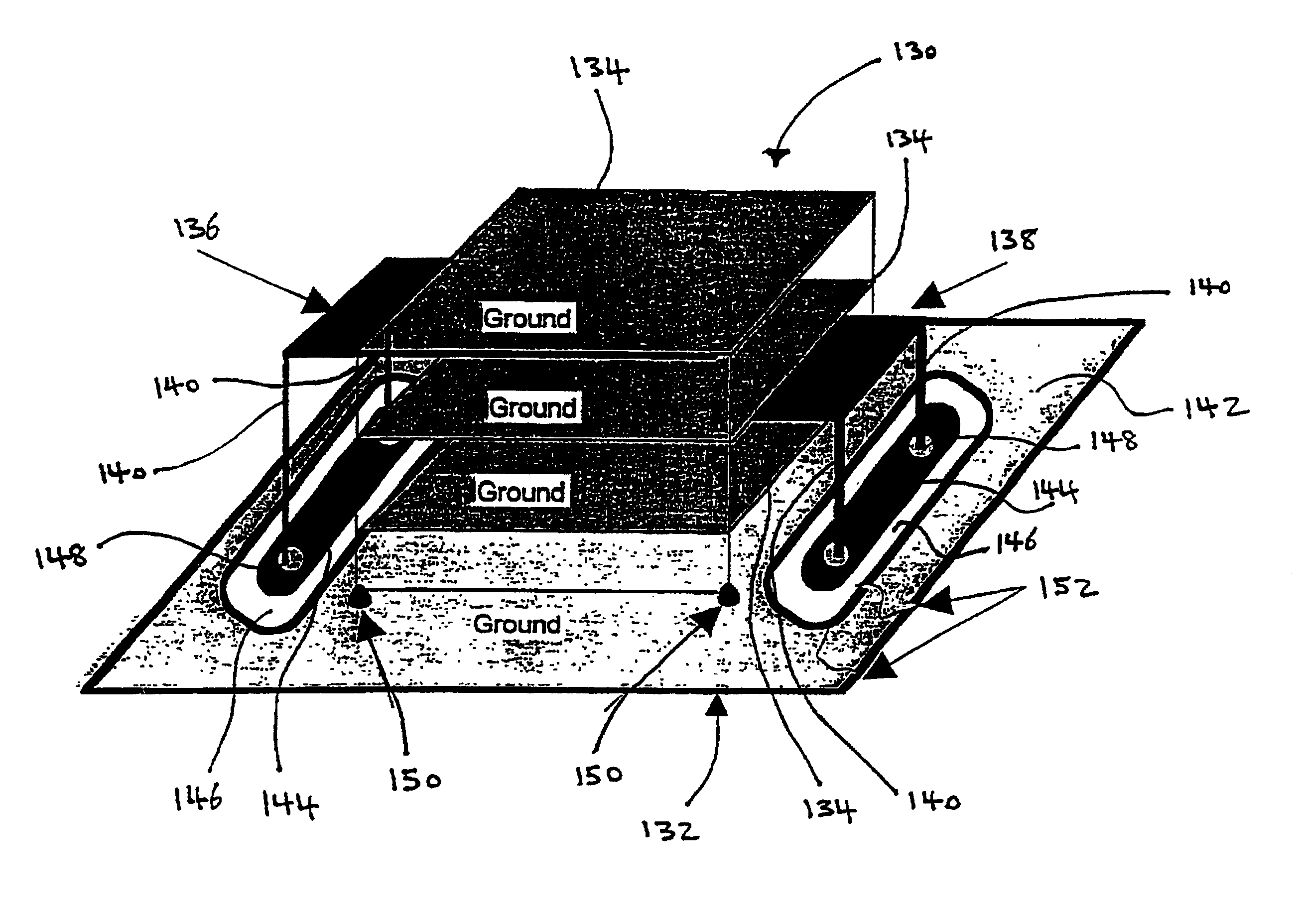
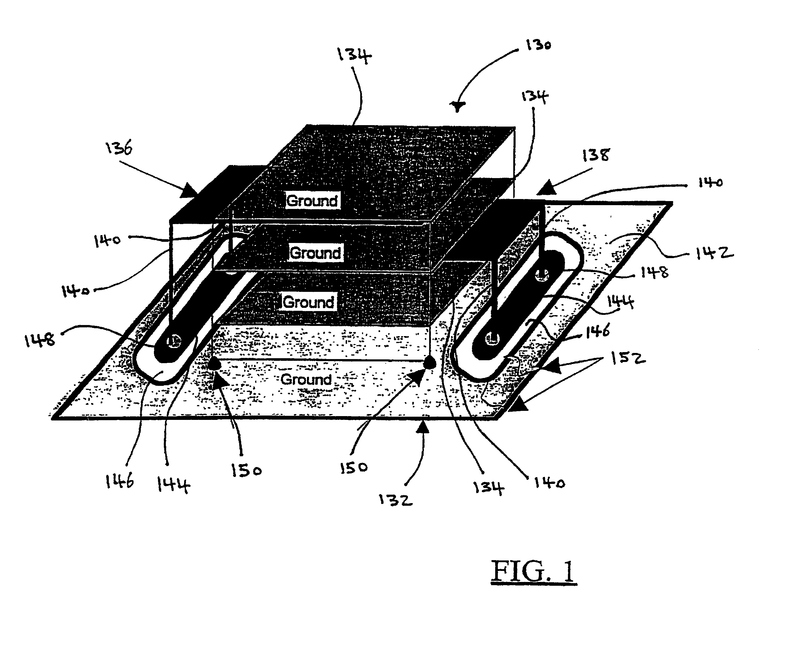
[0048]FIG. 1 shows the present invention in its simplest form. Component carrier 132 is shown coupled with a differential and common mode filter 130 having thru-hole leads 140 for electrical coupling to carrier 132. Differential and common mode filter 130 is disclosed in application Ser. Nos. 08 / 841,940; 09 / 008,769; and 09 / 056,379, incorporated herein by reference. Briefly, the structure of differential and common mode filter 130 will be described. Filter 130 consists of a first electrode 136 and a second electrode 138 which are separated by and electrically isolated from a plurality of ground layers 134 and each other. The particular architecture creates a line-to-line capacitor and two line-to-ground capacitors which provide for differential and common mode filtering and decoupling.

[0049]Because filter 130 is a somewhat fragile component, component carrier 132 provides a physical support to which filter 130 is electrically coupled. The first and second electrodes 136 and 138 each ...


PUM


Abstract

The present invention is a component carrier comprising a plate of insulating material having a plurality of apertures for accepting the leads of a thru-hole differential and common mode filter. Another embodiment comprises a surface mount component carrier comprised of a disk of insulating material having a plurality of apertures. The same concept for the above described carrier is also incorporated into several alternate embodiments, either independently or embedded within electronic connectors, or configured for use with electric motors. The overall configuration and electrical characteristics of the concepts underlying the present inventions are also described as an electrical circuit conditioning assembly which encompasses the combination of differential and common mode filters and component carriers optimized for such filters. The various embodiments of component carriers provide increased physical support and protection to differential and common mode filters and substantially improve the electrical characteristics of the filters due to the increased shielding provided by the carriers.

Description

TECHNICAL FIELD[0001]This application is a national stage application of international application PCT / US99 / 07653 filed Apr. 6, 1999. This application is a continuation-in-part of application Ser. No. 09 / 056,436 filed Apr. 7, 1998, now abandoned, which is a continuation-in-part of U.S. application Ser. No. 09 / 008,769 filed Jan. 19, 1998, now U.S. Pat. No. 6,097,581 which is a continuation-in-part of U.S. application Ser. No. 08 / 841,940, filed Apr. 8, 1997, now U.S. Pat. No. 5,909,305. This application also claims the benefit of U.S. Provisional Application No. 60 / 101,511 filed Sep. 23, 1998 and U.S. Provisional Application No. 60 / 103,759 filed Oct. 9, 1998. The present invention relates to electronic component carriers used in the manufacture of electronic equipment. More specifically, the invention relates to component carrier substrates used to protect electronic components from mechanical stresses associated with their handling and coupling within electronic equipment. The compon...

Claims


Application Information

Patent Timeline
IPC IPC(8): H05K7/10
CPCH01R13/7197H05K1/0243H01R23/6873H01R23/7073H05K1/141H05K2201/1006H05K3/3447H05K2201/0715H05K2201/09481H05K2201/0979H05K3/3442H01R12/724H01R13/658
Inventor ANTHONY, ANTHONY A.ANTHONY, WILLIAM M.
Owner X2Y ATTENUATORS L L C
Why Eureka
Try Eureka