Fixing apparatus

a technology of fixing apparatus and fixing roller, which is applied in the direction of electrographic process apparatus, induction heating, instruments, etc., can solve the problems of inability to operate the thermostat, inability to arrange the power line, and inability to start with some time delay, so as to achieve the effect of preventing excessive temperature rise of the heating roller and ensuring safety and reliability

Active Publication Date: 2006-01-31
KK TOSHIBA +1
View PDF8 Cites 3 Cited by
  • Summary
  • Abstract
  • Description
  • Claims
  • Application Information

AI Technical Summary

Benefits of technology

[0010]An object of the present invention is to provide a fixing apparatus that excels in safety and reliability, in which an excessive temperature rise of the heating roller can be prevented, without any delay, without using a thermostat and without arranging the power line around any component.

Problems solved by technology

The thermostat cannot operate the moment an excessive heating of the heating roller is detected.
Rather, it starts with some time delay.
This arrangement of the power line is undesirable in view of noise reduction and operation safety.

Method used


Image

  • Fixing apparatus
  • Fixing apparatus
  • Fixing apparatus

Examples


Embodiment Construction

[0018]An embodiment of the present invention will be described with reference to the accompanying drawings.

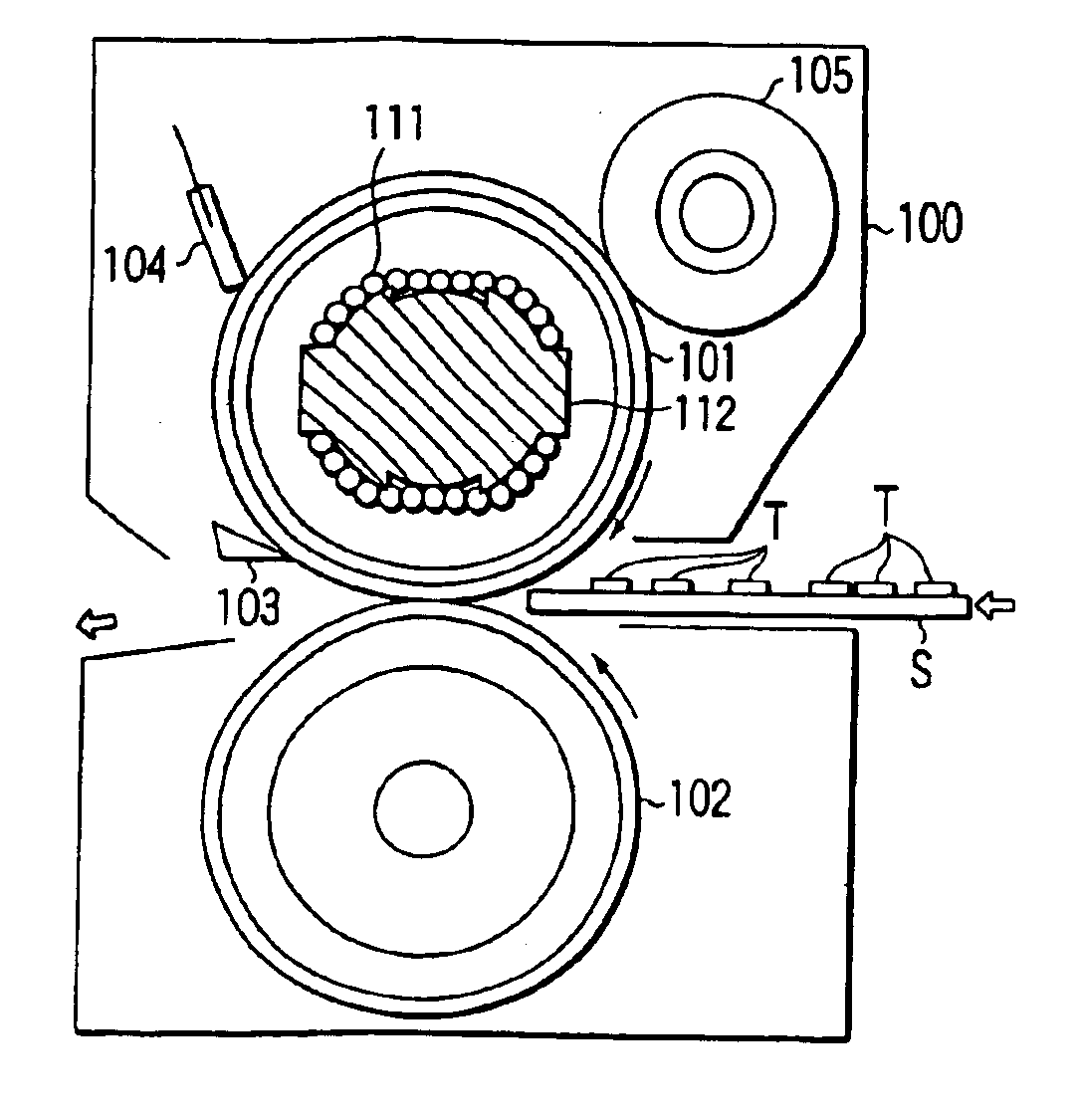
[0019]An image forming apparatus according to this invention is, for example, an electronic copier. The copier comprises a scanning unit, a process unit, and a fixing apparatus. The scanning unit optically reads the image printed on an original. The processing unit (unit 95, described later) forms, on a paper sheet, a toner image corresponding to the image read by the scanning unit. The fixing apparatus (apparatus 100, described later) heats the paper sheet, thereby fixing the toner image on the paper sheet. The structure of this image forming apparatus is disclosed in U.S. patent application Ser. No. 09 / 955,089 and will not be described in detail.

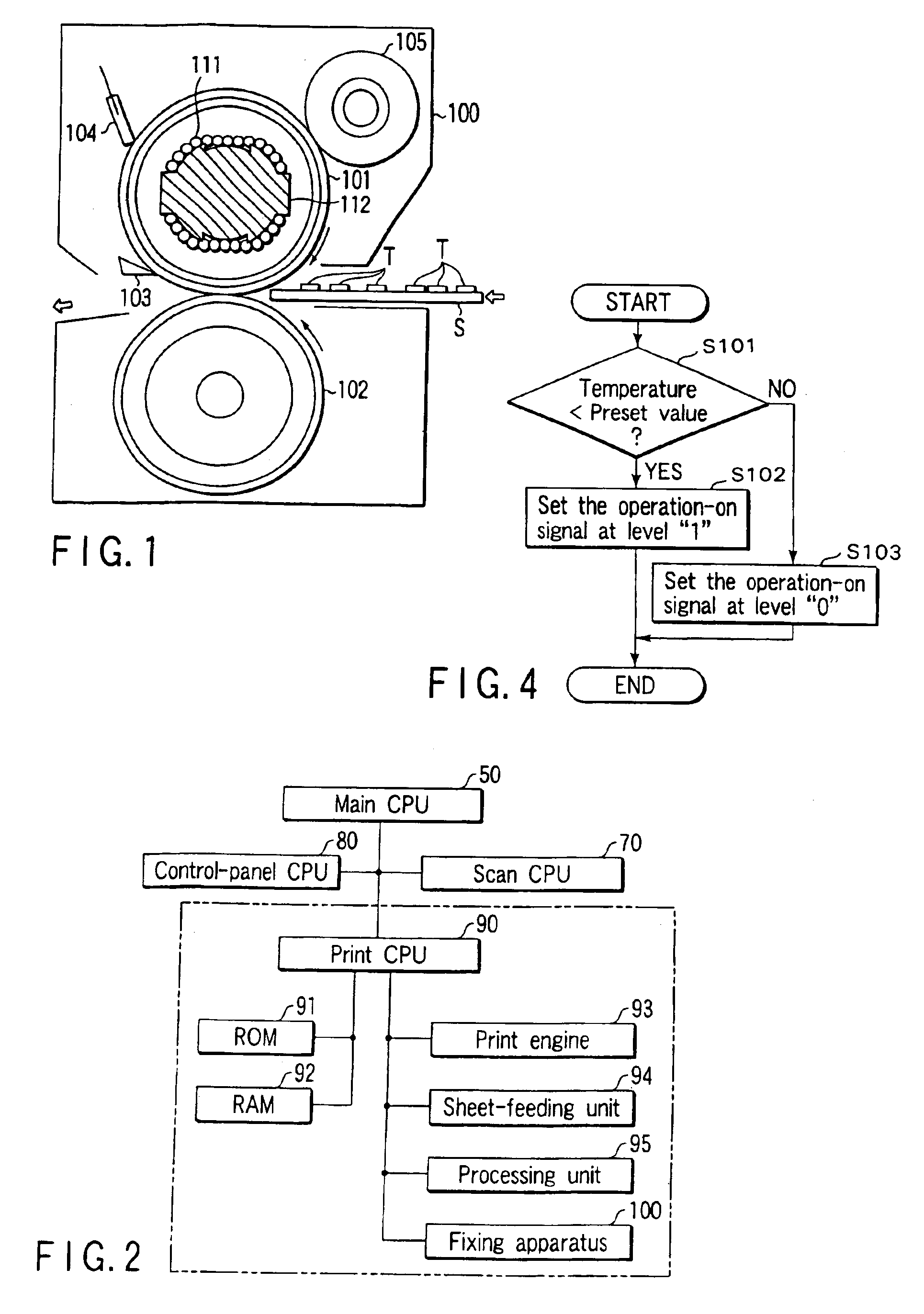
[0020]FIG. 1 depicts the fixing apparatus 100. As shown in FIG. 1, the fixing apparatus 100 comprises a heating roller 101 and a pressing roller 102. The heating roller 101 is located above the copy-sheet path. The pressing roller 102...


PUM


Abstract

A coil for generating a high-frequency magnetic field is provided in a heating roller. The coil is connected to a capacitor, constituting a resonant circuit. The resonant circuit is incorporated in a high-frequency wave generating circuit. A current-detecting circuit detects the current supplied to the high-frequency wave generating circuit. The supply of the current to the high-frequency wave generating circuit is controlled in accordance with the current detected by the current-detecting circuit and the logic level of an operation-on signal.

Description

CROSS-REFERENCE TO RELATED APPLICATIONS[0001]This application is based upon and claims the benefit of priority from the prior Japanese Patent Application No. 2002-215776, filed Jul. 24, 2002, the entire contents of which are incorporated herein by reference.BACKGROUND OF THE INVENTION[0002]1. Field of the Invention[0003]The present invention relates to a fixing apparatus designed for use in an image forming apparatuses such as copiers or printers and configured to fix developer images on paper sheets.[0004]2. Description of the Related Art[0005]Any image forming apparatus utilizing digital technology, such as an electronic copier, comprises a fixing apparatus. The fixing apparatus has a heating roller and a pressing roller. The pressing roller contacts the heating roller. A paper sheet with a toner image on it can be fed forward through the nip between the heating roller and the pressing roller. As the sheet is so fed, the toner image is fixed on the paper sheet by virtue of the hea...

Claims


Application Information

Patent Timeline
Patent Type & Authority Patents(United States)
IPC IPC(8): G03G15/20H05B6/06H05B6/14
CPCG03G15/2064
Inventor NEZU, YUKIHIRO
Owner KK TOSHIBA
Why Eureka
Try Eureka