
Connection

a technology for connecting pipes and drill pipes, applied in the direction of hose connections, screw threaded joints, manufacturing tools, etc., can solve the problems of increasing the risk of slipping, causing structural problems, and causing excessive deformation, so as to increase the tension of the connection, prevent ramping, and increase the locking action

Inactive Publication Date: 2006-01-31
HUNTING ENERGY SERVICES LLC
View PDF25 Cites 7 Cited by
  • Summary
  • Abstract
  • Description
  • Claims
  • Application Information

AI Technical Summary

Benefits of technology

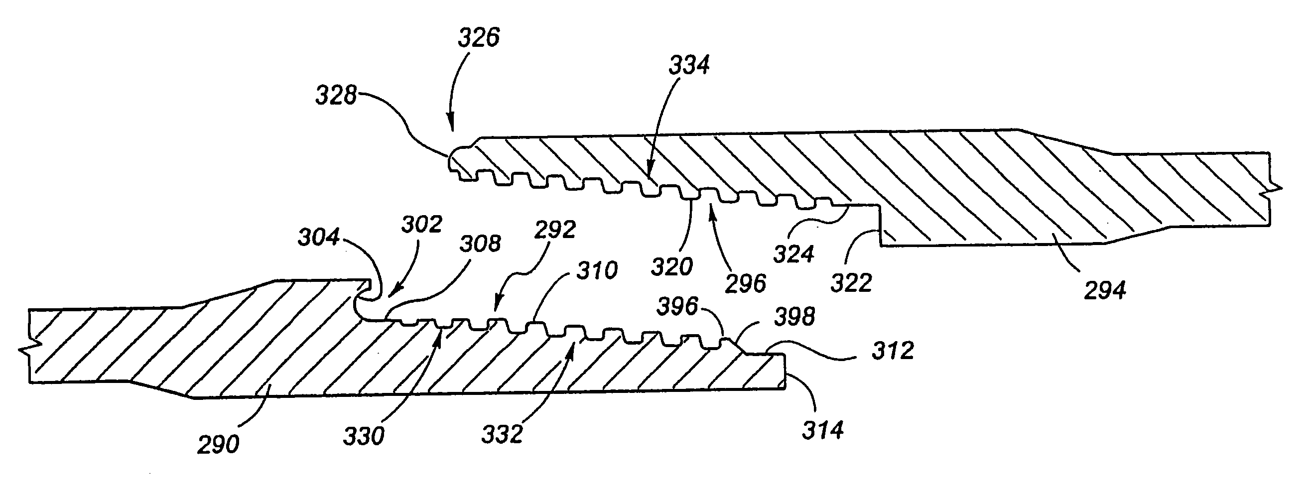
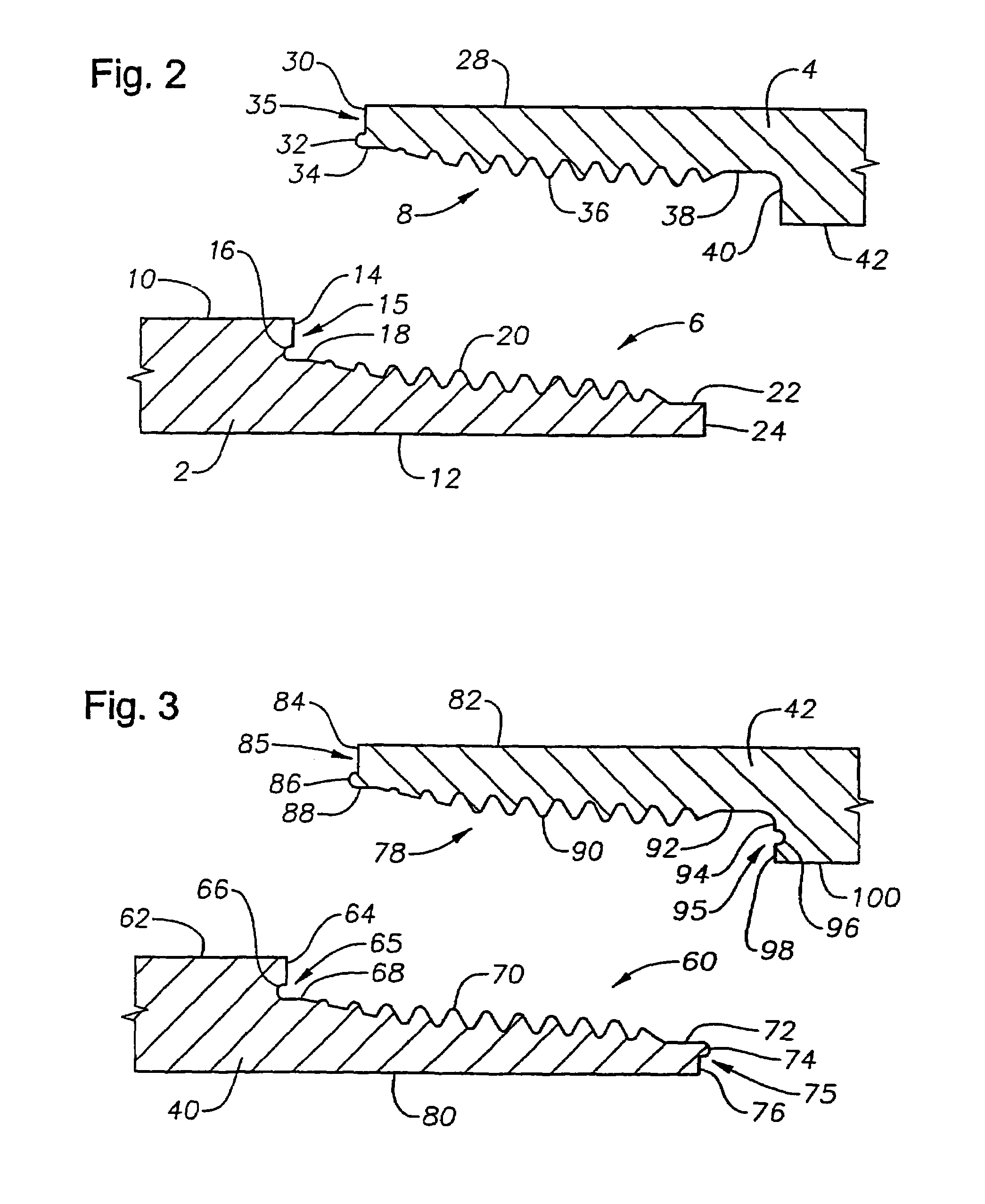
[0032]In the preferred embodiment, the pin connector includes an external groove at the base of the external threads for receiving a protuberance on the terminal end of the box connector. The protuberance has a cross-section in the shape of a bull nose or radius which extends across the terminal end of the box connector. The groove on the pin connector has a radius sized to receive the protuberance upon the make-up of the connection. The mating protuberance and groove form a non-sliding engagement to substantially eliminate the sliding between the mating groove and protuberance.
[0043]The thread profile of the present invention addresses all of the critical elements of the working environment and the weaknesses of the prior art thread designs. The new thread profile prevents ramping, rocking and fatigue of the connection and also allows increased torque and most importantly increase the life of the pipe.

Problems solved by technology

The operator minimizes the amount of fluid that is circulated through the drill string because too much fluid into the surrounding earth bore is undesirable.
If too much fluid is circulated through and around the drill string, the fluid begins to wash out the sand, dirt, and earth causing a washout underneath the obstacle or structure, such as a highway or waterway, under which the bore hole is being drilled.
Structural problems will be created if a void is formed underneath a highway or some other structure.
First, once a thread begins to deform, further deformation is usually exponentially increased thereafter.
Second, once the thread has deteriorated, the entire drill string must be disregarded since the length of the drill string has very limited variance.
Third, failure of the thread while the drill string is in the process of actually drilling a bore hole will cause substantial monetary damage.
Despite these designs, when a drill string member has a thread that is used in multiple applications for the drilling of bore holes in the utility and pipeline industries, the mating shoulders may become flared due to over torquing.
Also, the prior art designs result in the thread profile becoming deformed which in turn causes the external and internal thread design profiles to lose their make-up capability and results in premature failure.
Once deformation begins, continued use exponentially increases mating problems between cooperating tubular members.
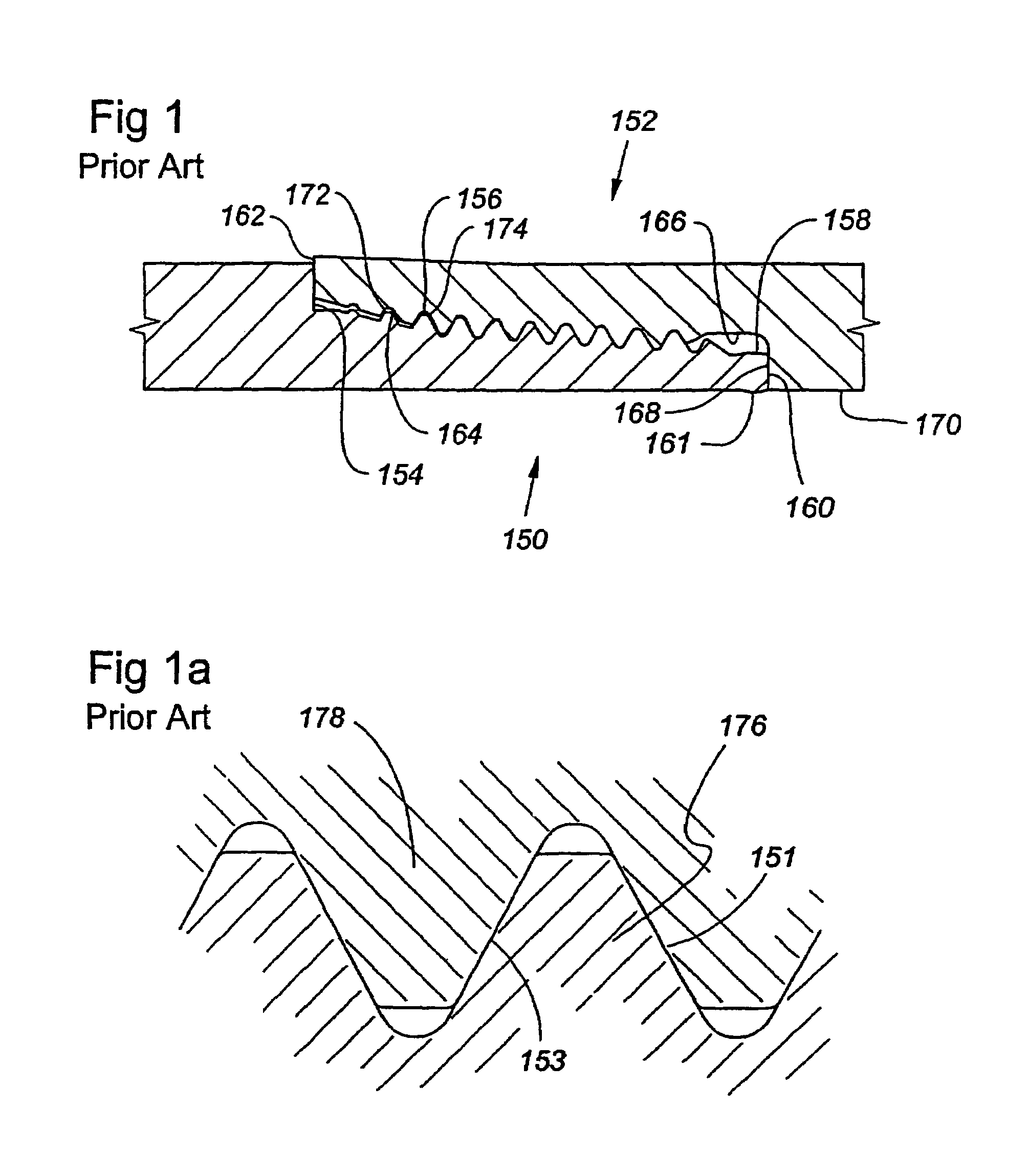
FIG. 1 illustrates a prior art connection and the inherent problem with multiple fastening and unfastening of prior art connections in the utility industry due to over torquing and cycling of the box and pin.
Thus, as the connection is placed under stress and incurs a cycling motion, the connection fatigues and breaks.
The tubular members rocking on each other cause the connection to become loose.
The over torquing situation will also cause the thread profiles to no longer match properly.
However, the connection has very little compression capability.
However, many applications, such as deviated settings, produce several abrupt dog legs or kinks in the borehole due to the operator making abrupt changes in the direction of drilling.
Tortuosity substantially increases the cyclic bending, torque and drag on the drill string.
The smaller the radius of the bend in the bore hole, the greater fatigue that will be placed on the pin.
The ramping of the threads cause yielding of the material and thus damage the connection.
Rocking causes fatigue and pin breakage.
As the reamer engages obstacles in the drilling path, bends and torque are placed on the connections causing the threads to open and close.
These repetitive cycles with sliding shoulders provides a continuing fatigue at the mid-portion of the pin.
This causes substantial stress and causes the pin to break off at the connection.
During one half of the cycle the pin is bent one way and then during the other half of the cycle it is bent the other way causing it to fatigue and break.
This back and forth action causes tremendous fatigue.
All of these factors induce rapid fatigue in the connection.
Also, during the drilling process, a large amount of compressive force is placed on the drill string which tends to drive the terminal box end outwardly as the surfaces' slide.
However, the mid-portion of the threads remain tight.
Then at every cycle, the counter-stretching back and forth begins to fatigue the connection.
If the environment is very bad and if you have an inexperienced operator, the operator tends to over-compensate and steers too hard.
This causes a tortuosity in the hole being drilled.
This places the drill string in a very serious bind as it is rotated through the bore hole.
Another of the problems of the prior art connection is its ability to withstand high torque.
An extreme amount of torque is applied to the connection as compared to the small diameter of the pipe causing a large amount of torque to then be applied to a small diameter drilling string.
Further, as the pipe string passes through severe multiple bends, high inertia torque is placed on the connections as the pipe string passes around obstacles and forms severe multiple bends.
In the utility industry, often the operators are inexperienced and force the drill string to achieve a bore hole from point A to point B and do not drill a smooth bore hole.
Once the stretching exceeds the limit, then the connection begins to fatigue and will break.

Method used


Image

  • Connection
  • Connection
  • Connection

Examples


Embodiment Construction

[0045]For a detailed description of a preferred embodiment of the invention, reference will now be made to the accompanying drawings wherein:

[0046]FIG. 1 is a cross-sectional view of a prior art connection showing flared threads;

[0047]FIG. 1A is a cross-sectional enlarged view of prior art API threads for the connection of FIG. 1;

[0048]FIG. 2 is a cross-sectional view of a first preferred embodiment of the present invention;

[0049]FIG. 3 is a cross-sectional view of a second preferred embodiment of the present invention;

[0050]FIG. 4 is a cross-sectional view of a third preferred embodiment of the present invention;

[0051]FIG. 5 is an illustrated view of three sections of a tubular string, with the individual tubular members having the connection shown in FIG. 3 of the present invention;

[0052]FIG. 6 is a cross-sectional view of the pin and box connectors of another preferred embodiment of the present invention;

[0053]FIG. 7 is a cross-sectional view of the pin and box connectors of FIG....


PUM


Abstract

A drill string includes a plurality of tubular members each having a connection with a pin connector and a box connector on adjacent tubular members. The pin connector has an external thread with negative load flanks and positive stab flanks, adapted for threadingly engaging an internal thread second threads with negative load flanks and positive stab flanks on the box connector of the adjacent tubular member. The positive stab flanks have corner radiuses and the negative load flanks have radiuses forming a S-shape. The pin connector has an outer groove for receiving a protuberance on the terminal end of the box member forming locking shoulders. The protuberance and groove have contoured surfaces providing large metal-to-metal contact for preventing the contoured surfaces from sliding during over-torquing and cyclic bending of the drill string. The negative load flanks and locking shoulders lock the connection together. The negative load flanks absorbing the tension and the locking shoulders absorbing the compression on the connection.

Description

CROSS-REFERENCE TO RELATED APPLICATIONS[0001]The present application is a divisional of U.S. patent application Ser. No. 09 / 371,562 filed Aug. 10, 1999 now U.S. Pat. No. 6,485,063 and entitled “Connection” which is a continuation-in-part of U.S. patent application Ser. No. 08 / 972,516 filed Nov. 18, 1997 now U.S. Pat. No. 6,047,997 and entitled “Connection” which is a continuation-in-part of U.S. patent application Ser. No. 08 / 648,406, filed May 15, 1996, now abandoned and entitled “Novel Locking Design”, both hereby incorporated herein by reference.BACKGROUND OF THE INVENTION[0002]This invention relates to a connection for drill pipe and more particularly, pin and box connectors disposed on the ends of tubular members for connecting the tubular members for the drilling of bore holes in the pipeline and utility industry.[0003]Drill strings are specifically designed for the installation of telephone lines, fiber optic cable, sewage lines, water lines, and similar installations relatin...

Claims


Application Information

Patent Timeline
IPC IPC(8): B21D39/00F16L15/00E21B17/042F16L15/06F16L15/08
CPCE21B17/042F16L15/08F16L15/06Y10T29/49881Y10T29/49826
Inventor OLIVIER, HUEY P.
Owner HUNTING ENERGY SERVICES LLC
Learn More