
Control device for vehicles

Active Publication Date: 2006-01-24
AISIN AW CO LTD
View PDF9 Cites 19 Cited by
  • Summary
  • Abstract
  • Description
  • Claims
  • Application Information

AI Technical Summary

Benefits of technology

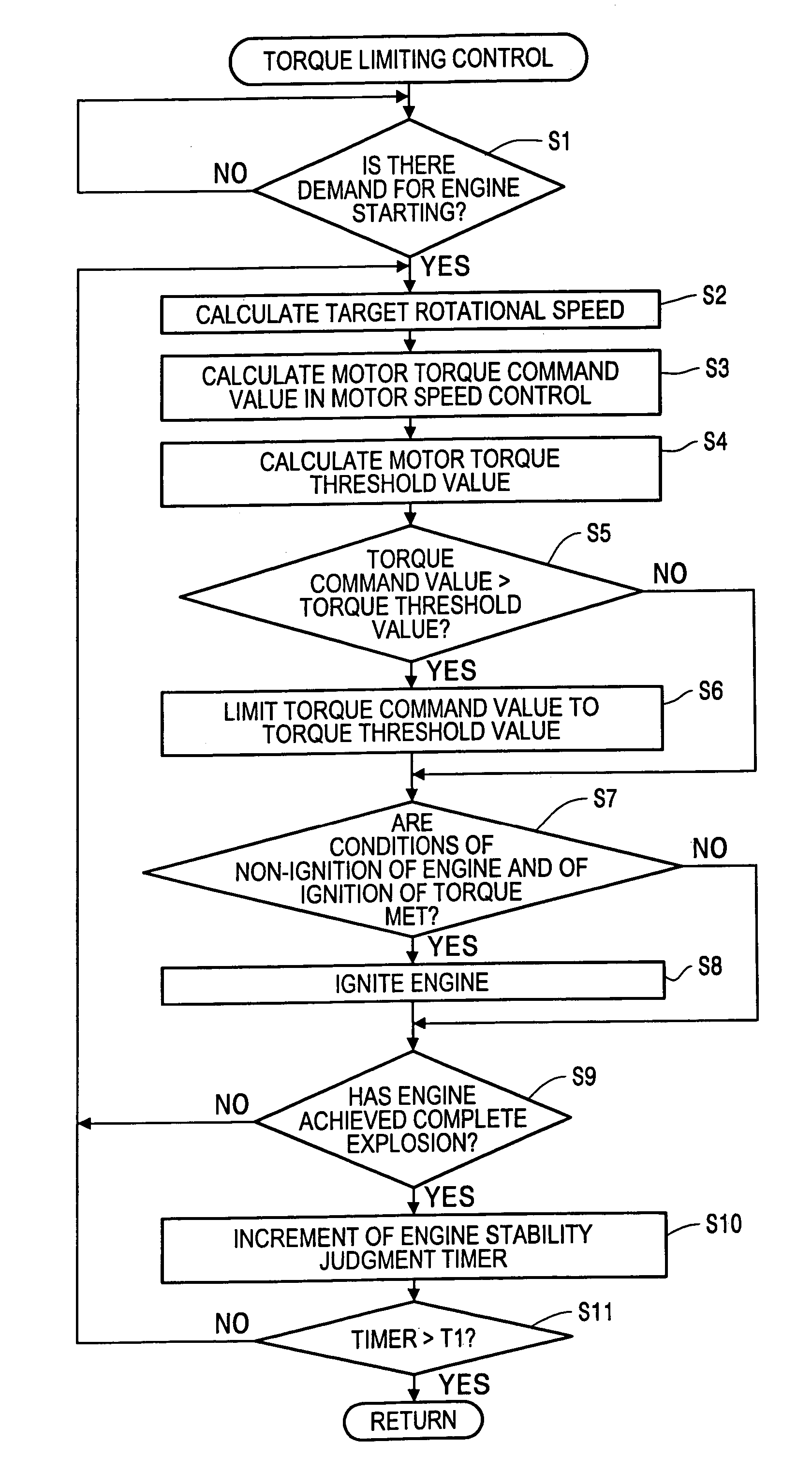
[0008]The invention thus provides a control device for a vehicle that is constructed to suppress a surplus torque which is liable to be generated through a torque converter at the time of output of an engine torque after an output of a motor torque in order to prevent the generation of wheelspin or the like.
[0011]According to the first exemplary aspect of the invention, the controller controls a drive torque of a motor in a manner to set the drive torque of the motor within a range of a maximum input torque of a transmission calculated on the basis of a torque ratio of the torque converter when the driving of the engine is started after the driving of the motor is started. With, for example, an automatic transmission, it is thus possible to eliminate shocks created by frictional engagement elements that slide and then abruptly engage with one another.

Problems solved by technology

The starting control restricts the maximum torque because when a motor is used to crank the internal combustion engine for starting in a cold condition in which the engine temperature is low, an engine speed is not readily increased due to a high viscosity of a lubricating oil.
The battery is thus wastefully consumed until a predetermined engine speed is reached.
Incidentally, vehicles constructed such that the internal combustion engine is started by motor torque possibly suffer from a disadvantage in that a surplus torque is generated at the start of an engine that succeeds the driving of the motor.
The surplus torque causes wheelspin and damage on a transmission.

Method used


Image

  • Control device for vehicles
  • Control device for vehicles
  • Control device for vehicles

Examples


Embodiment Construction

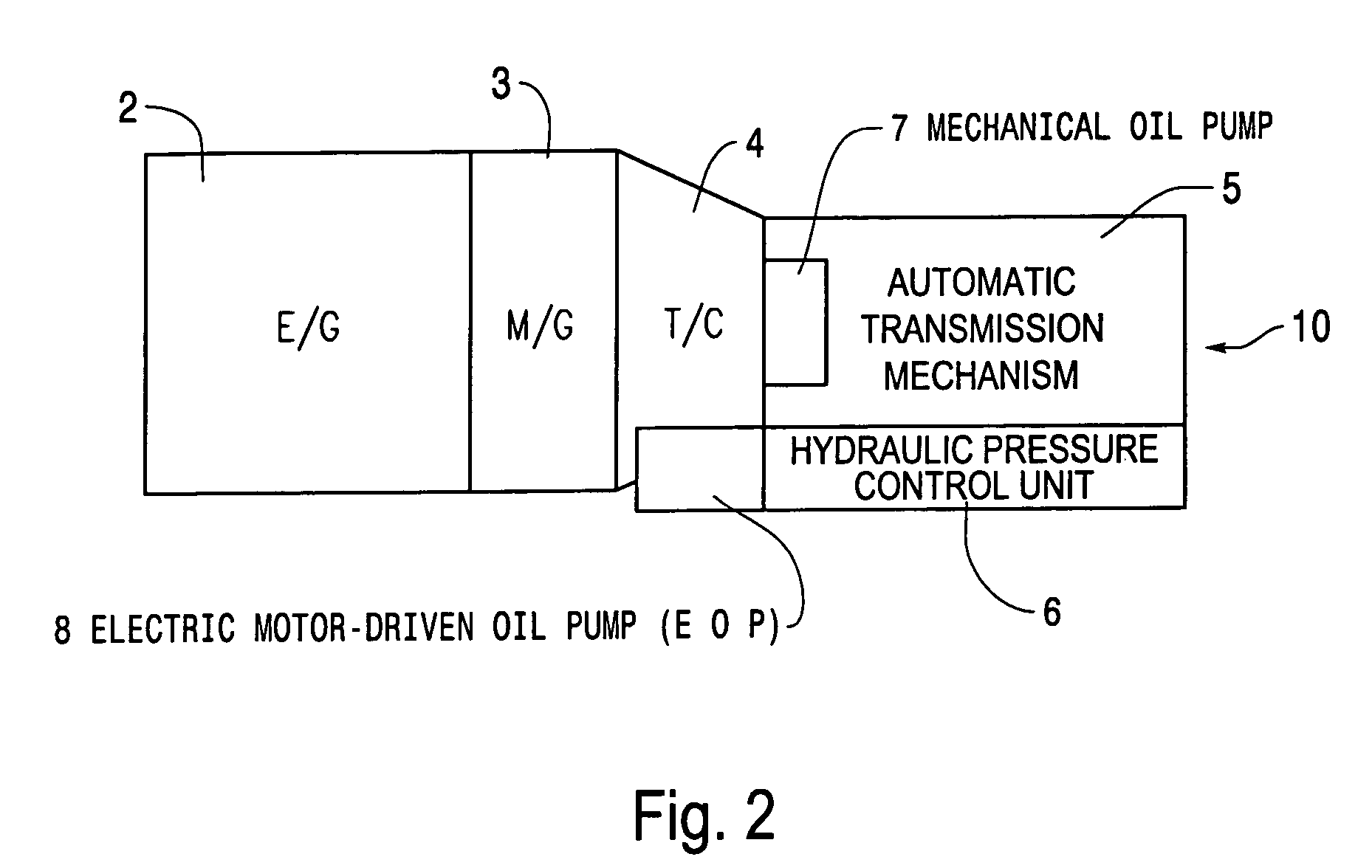
[0022]A first embodiment of the invention will be described below with reference to the drawings. First, referring to FIGS. 2 and 3, an explanation will be given to a drive system of a hybrid vehicle, and an automatic transmission mechanism provided therein, to which a control device according to the invention is applicable. FIG. 2 is a schematic block diagram showing a drive system of a hybrid vehicle, and FIG. 3 is a view showing details of an automatic transmission mechanism 5, to which the invention is applicable. FIG. 3A being a skeleton view of the automatic transmission mechanism 5, and FIG. 3B being a working table thereof. In addition, engine drive start in the embodiment means that an engine is started and begins to output a positive torque.

[0023]As shown in FIG. 2, a drive source is composed of an internal combustion engine (E / G) (referred simply below to as “engine”) 2 and a motor / generator (M / G) (referred simply below to as “motor”) 3, and the drive force is output to a...


PUM


Abstract

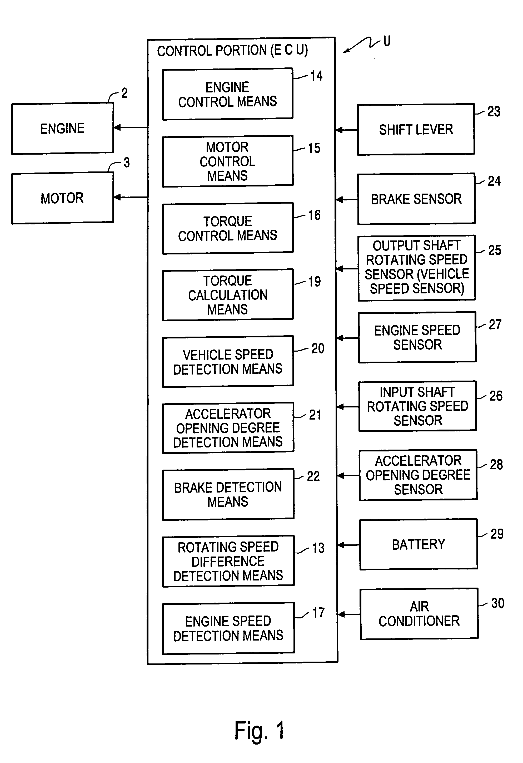
A control device for a vehicle including a motor, an engine, wherein the motor can be drivingly connected with the engine, a torque converter, a transmission mechanism for transmitting the drive torque, which is transmitted via the torque converter from the engine and the motor, to drive wheels, and a controller that controls a driving state of the motor, controls a driving state of the engine, and outputs a torque reduction command for controlling a drive torque of the motor in order to place the drive torque of the motor within a maximum input torque of the transmission mechanism, wherein the maximum input torque is calculated based on a torque ratio of the torque converter when the engine begins driving after the motor begins driving.

Description

[0001]The disclosure of Japanese Patent Application No. 2002-382587 filed on Dec. 27, 2002, including the specification, drawings and abstract are incorporated herein by reference in their entirety.BACKGROUND OF THE INVENTION[0002]1. Field of Invention[0003]The invention relates to a control device for a vehicle.[0004]2. Description of Related Art[0005]There exists parallel hybrid systems in which both an engine and a motor / generator are attached to a transmission. Drive forces from both the engine and the motor / generator are transmitted to the transmission at the time of departure and acceleration, the motor / generator functions as a generator when a vehicle runs on a downhill road and when the vehicle brakes to make up for the engine brake effect, and a braking energy is recovered to enhance fuel consumption and to reduce a discharge of exhaust gas (see, for example, JP-A-9-215270).[0006]In a vehicle with the hybrid system (HEV: Hybrid Electric Vehicle), there exists a starting con...

Claims


Application Information

Patent Timeline
IPC IPC(8): B60K1/02B60K6/485B60K6/547B60K28/16B60L50/16B60W10/06B60W10/08B60W10/10B60W20/00F16H3/66F16H59/46
CPCB60K6/485B60K28/165B60W10/06B60W10/08B60W20/00F16H3/663B60K6/54Y10T477/69395B60L2240/421B60L2240/486B60W2510/1005B60W2510/1045B60W2530/10B60W2530/16B60W2530/20B60W2550/12B60W2550/148B60W2710/081B60W2710/105F16H35/10F16H61/686F16H2059/467F16H2200/0047F16H2200/201F16H2200/2025Y02T10/6226Y02T10/6286Y02T10/642Y10T477/30Y10T477/23B60W2552/40B60W2555/20Y02T10/62Y02T10/64B60W2050/0022B60W2050/001B60W30/18027B60W10/04B60W2510/1025B60W10/023B60W10/026
Inventor KOBAYASHI, YASUHIKONAKAMORI, YUKINORITAKAMI, SHIGEKIKAYUKAWA, ATSUSHITAJIMA, YOICHIMURASE, YOSHITAKA
Owner AISIN AW CO LTD
Learn More