
Method for enhancing the communication capability in a wireless telecommunication system

a wireless telecommunication system and communication capability technology, applied in the field of wireless telecommunications system enhancement, can solve the problems of radio transmission subjected to rayleigh fading, multipath and other noise-inducing effects, and known to be very time-dependent, and achieve the effect of enhancing functionality

Inactive Publication Date: 2006-01-03
MOTOROLA SOLUTIONS INC
View PDF10 Cites 64 Cited by
  • Summary
  • Abstract
  • Description
  • Claims
  • Application Information

AI Technical Summary

Benefits of technology

The present invention provides a method for improving communication capabilities of a communication unit by using multiple communication units. This is achieved through a discovery and coordination protocol where wireless devices discover a proximal user and coordinate amongst themselves to achieve enhanced functionality. The technical effect of this invention is increased operational capabilities of a particular UE or communication system.

Problems solved by technology

In addition, these factors are known to be very time-dependent, i.e. the factors vary widely over time.
Furthermore, as open communication systems are designed to share a finite communication resource, amongst a large number of subscriber devices, the subscriber devices are designed with operation and functionality limitations, such as a maximum data rate that they can transmit.
This leads to inefficiency, as perceived by the user as well as with regard to the operation of the system.
In a wireless communication network, it is well known that radio transmissions are subjected to rayleigh fading, multipath and other noise-inducing effects.
As particular transmissions require increased reliability, such as emergency calls, these transmissions are provided with increased amounts of error protection and thereby redundancy.
Again, this is an inefficient use of what is always a limited resource.
However, a major disadvantage with ODMA is that it is complex.
Furthermore, ODMA requires a substantial amount of signalling resource, to facilitate the relaying of communications between the directly coupled cellular units.
Therefore, due to the above difficulties with ODMA, it is unlikely that such a complex and resource-hungry solution would be acceptable in an open communication standard.

Method used


Image

  • Method for enhancing the communication capability in a wireless telecommunication system
  • Method for enhancing the communication capability in a wireless telecommunication system
  • Method for enhancing the communication capability in a wireless telecommunication system

Examples


embodiment 1

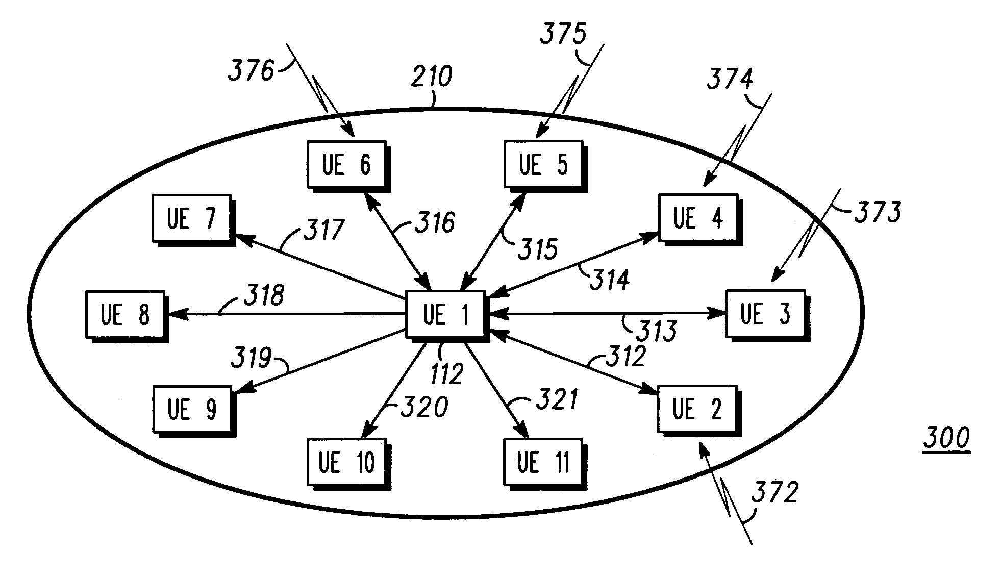
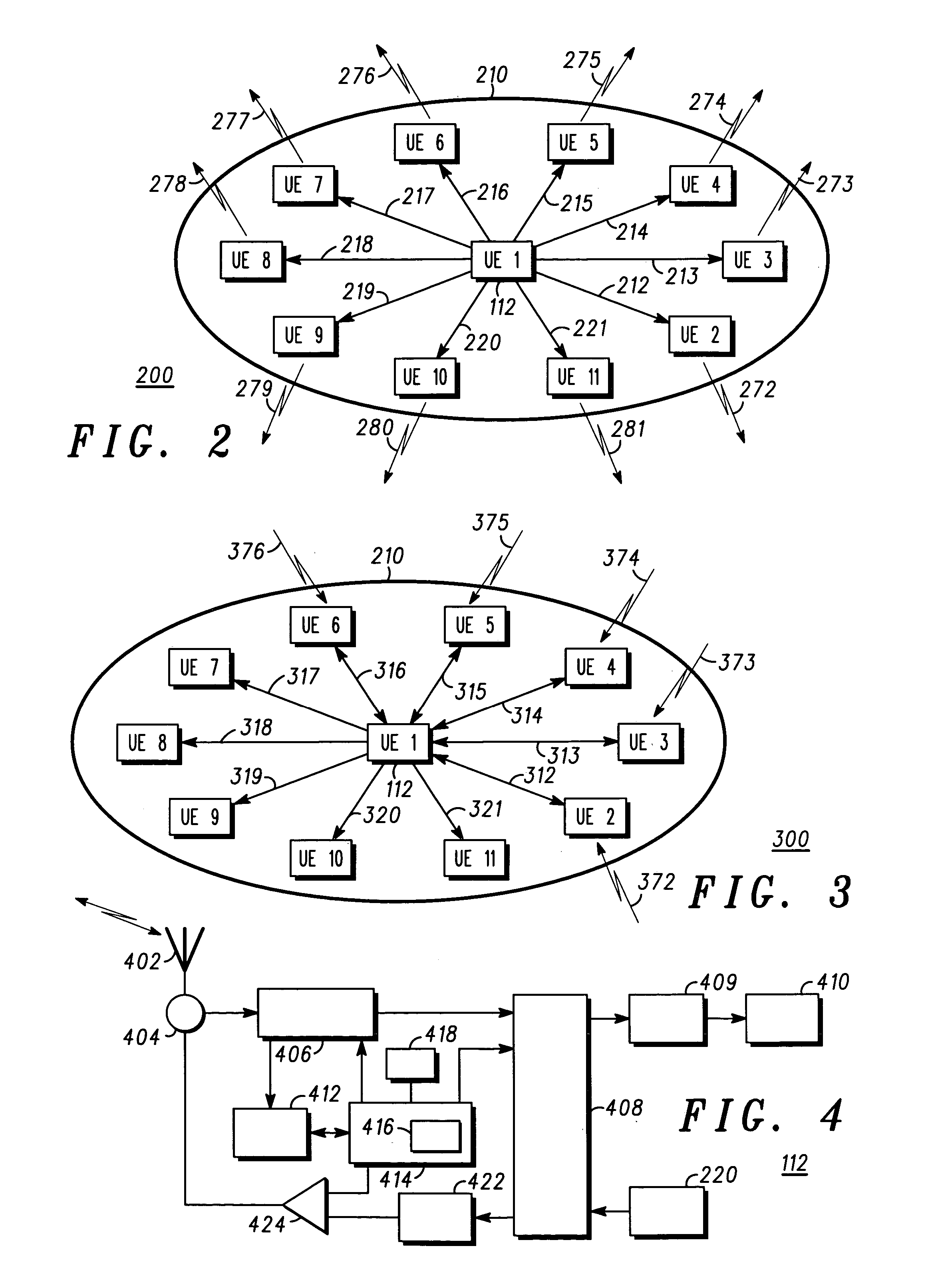
[0055]Referring now to FIG. 2, a diagram of an uplink communication configuration 200, for example a configuration of a plurality of user equipment (UE) of FIG. 1 is shown, the configuration being adapted to support the inventive concepts of a first embodiment of the present invention. In accordance with the first embodiment of the present invention, a UE, say UE-1112 wishes to initiate an enhanced functionality mode of operation. Such enhanced functionalities may include a desire to send a large amount of data, or high priority data such as an emergency call that is needed to be received in a short period of time, or poor signal quality conditions. Such a transmission will occur on uplink channels.

[0056]In order to initiate the enhanced functionality mode of operation, UE-1112 sets itself up as the ‘master’ communication unit in the first embodiment, in order to control the communication with the other UEs (UEs 2–11) that it uses for its uplink communication.

[0057]As shown in FIG. ...

embodiment 2

[0062]In accordance with a second embodiment of the present invention, a group of independent wireless devices are identified and coordinated (aggregated) using, for example in a wireless domain a short-range wireless system such as provided in the adjunct Bluetooth system.

[0063]By forming a ‘dynamic’ group based on proximal location via a short-range adjunct bluetooth system, any of the users UEs 1–11 may then benefit from using the capabilities of one or more of the other subscriber units within the group. This is in contrast to the first embodiment where a particular UE dynamically sets up a group to operate in a master-slave configuration for one or more specific tasks.

[0064]The provision, in the second embodiment, of such a larger communication “pipe” for use by any of the UEs in a group leads to, inter-alia, increased efficiency, for example, using a higher peak data-rate over the air interface for a packet data transmission.

[0065]A group of proximal users can co-operate for a...

embodiment 3

Emergency Call

[0076]In a yet further embodiment of the present invention, a further enhanced uplink application is provided. A large number of remote communication units now offer emergency call facilities, namely the ability to make a high priority call to a central receiving station. Examples of emergency calls include a call to the Emergency services in the case of say a cellular phone, or a call to the dispatcher in the case of a mobile radio.

[0077]The inventors of the present invention have recognised a further functionality enhancing operation in the re-use of selected (or random) neighboring UEs for emergency calls. As an example, let us consider the case when the user of the UE wishes to make an emergency call. However, the UE may not be within coverage range, say, of its serving Node B, and therefore it is unable to contact the network.

[0078]The inventors of the present invention have envisaged that the user / UE could request other selected or random neighboring UEs to set u...


PUM


Abstract

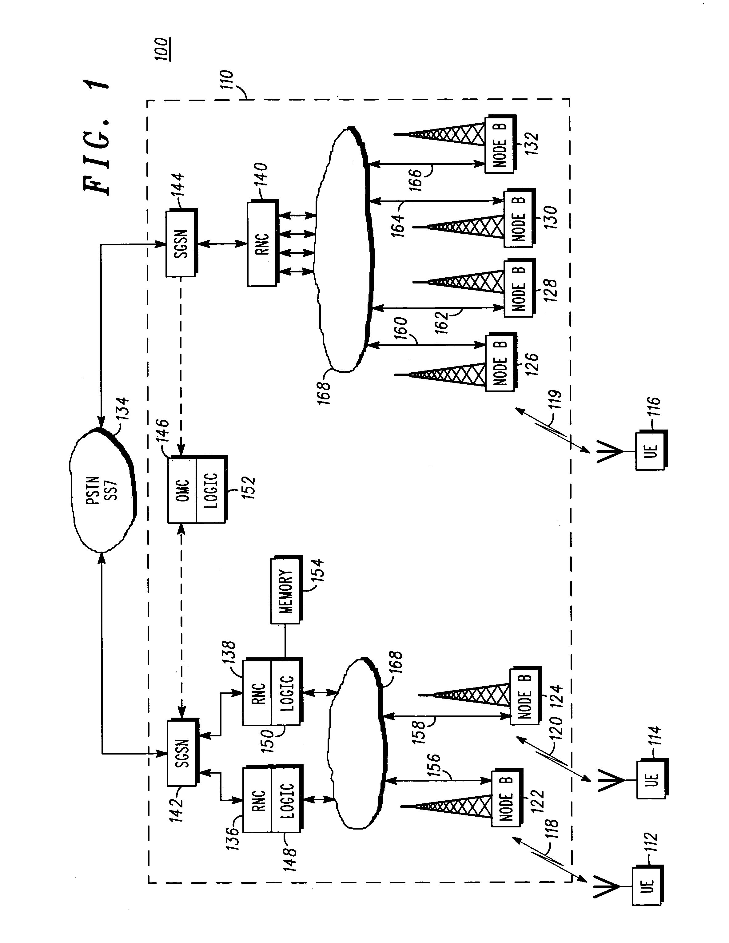
A method of enhancing a communication capability of a communication unit (112), operating in a communication system (100) that facilitates communication to and / or from a plurality of communication units. The method includes the step of operably coupling a first communication unit (112) to one or more neighboring communication units (114, 116) such that said communication unit is able to utilize at least one operational capability of one or more of its neighboring communication units to enhance communication to and / or from said first communication unit.

Description

FIELD OF THE INVENTION[0001]This invention relates to using multiple subscriber units to create several architecture and subscriber unit enhancing functions, enhanced data rates and improved reliability in existing or future wireless, or integrated wireless and fixed, communication systems.BACKGROUND OF THE INVENTION[0002]Wireless communication systems, for example cellular telephony or private mobile radio communication systems, typically provide for radio telecommunication links to be arranged between a plurality of base transceiver stations (BTSs) and a plurality of subscriber units, often termed mobile stations (MSs).[0003]The communication link from a BTS to a MS is generally referred to as a down-link communication channel. Conversely, the communication link from a MS to a BTS is generally referred to as an up-link communication channel.[0004]In a wireless communication system, each BTS has associated with it a particular geographical coverage area (or cell). The coverage area...

Claims


Application Information

Patent Timeline
Patent Type & Authority Patents(United States)
IPC IPC(8): H04B7/00H04B15/00H04B7/15H04B7/185H04Q7/20H04B7/26H04L12/28H04L12/56H04W4/08
CPCH04B7/2606H04W4/08H04W88/04H04W8/005
Inventor GARANI, PRADEEPVILLION, MATHIEUKOTZIN, MICHAELOWEN, RAY
Owner MOTOROLA SOLUTIONS INC
Learn More