
Laser diode module

Inactive Publication Date: 2006-01-03
OPNEXT JAPAN INC
View PDF16 Cites 0 Cited by
  • Summary
  • Abstract
  • Description
  • Claims
  • Application Information

AI Technical Summary

Benefits of technology

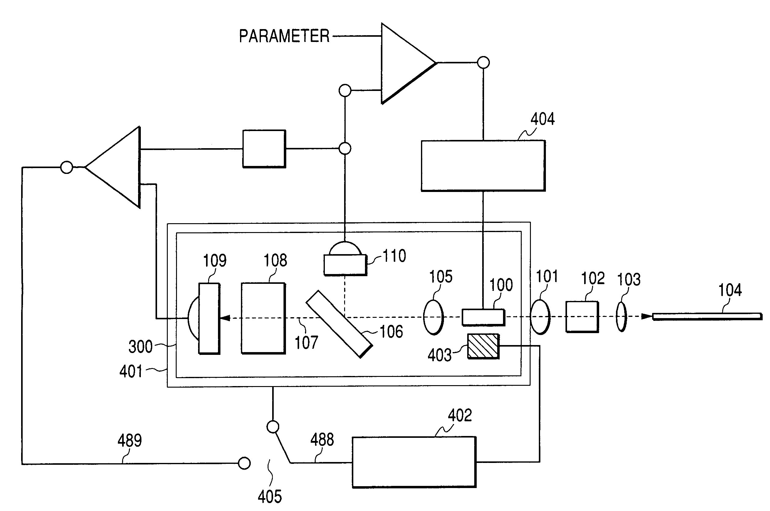
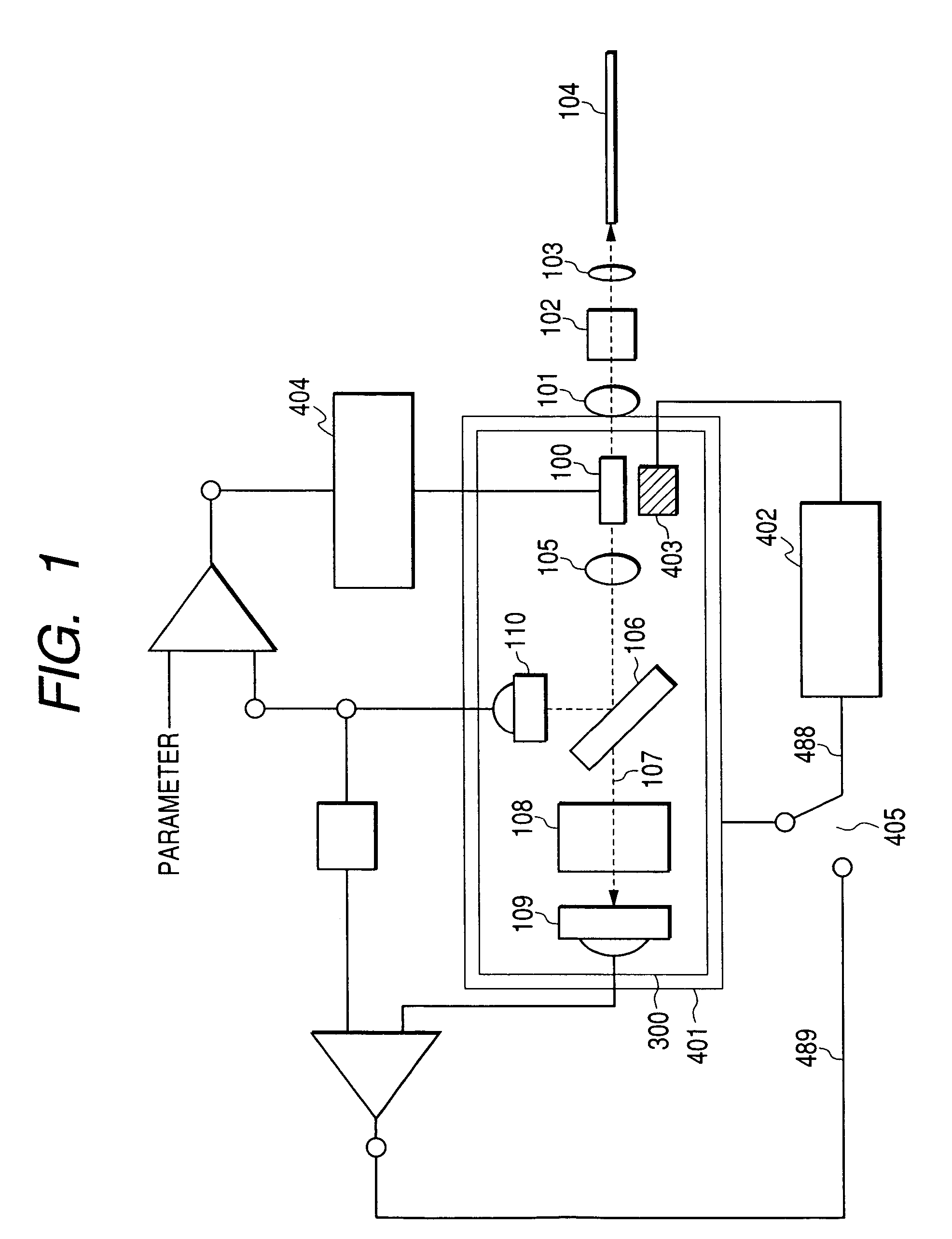
[0008]A basic form of the present invention consists of a laser diode module that comprises at least a laser diode device; a first detector element for receiving, directly or indirectly, a first light beam that is obtained when at least one of the light emissions of said laser diode device is divided into two light portions, each traveling in a different direction; a second detector element for receiving a second light beam that comprises the other of the divided light beams at least via a wavelength selective member; and means for controlling the lasing wavelength of the above-mentioned laser diode device on the basis of outputs of the above-mentioned first and second-photo detector elements, wherein a gap between the above-mentioned laser diode device and the above-mentioned wavelength selective member is formed so as to constitute an optical resonator with multi-interference eliminated or alleviated therein.
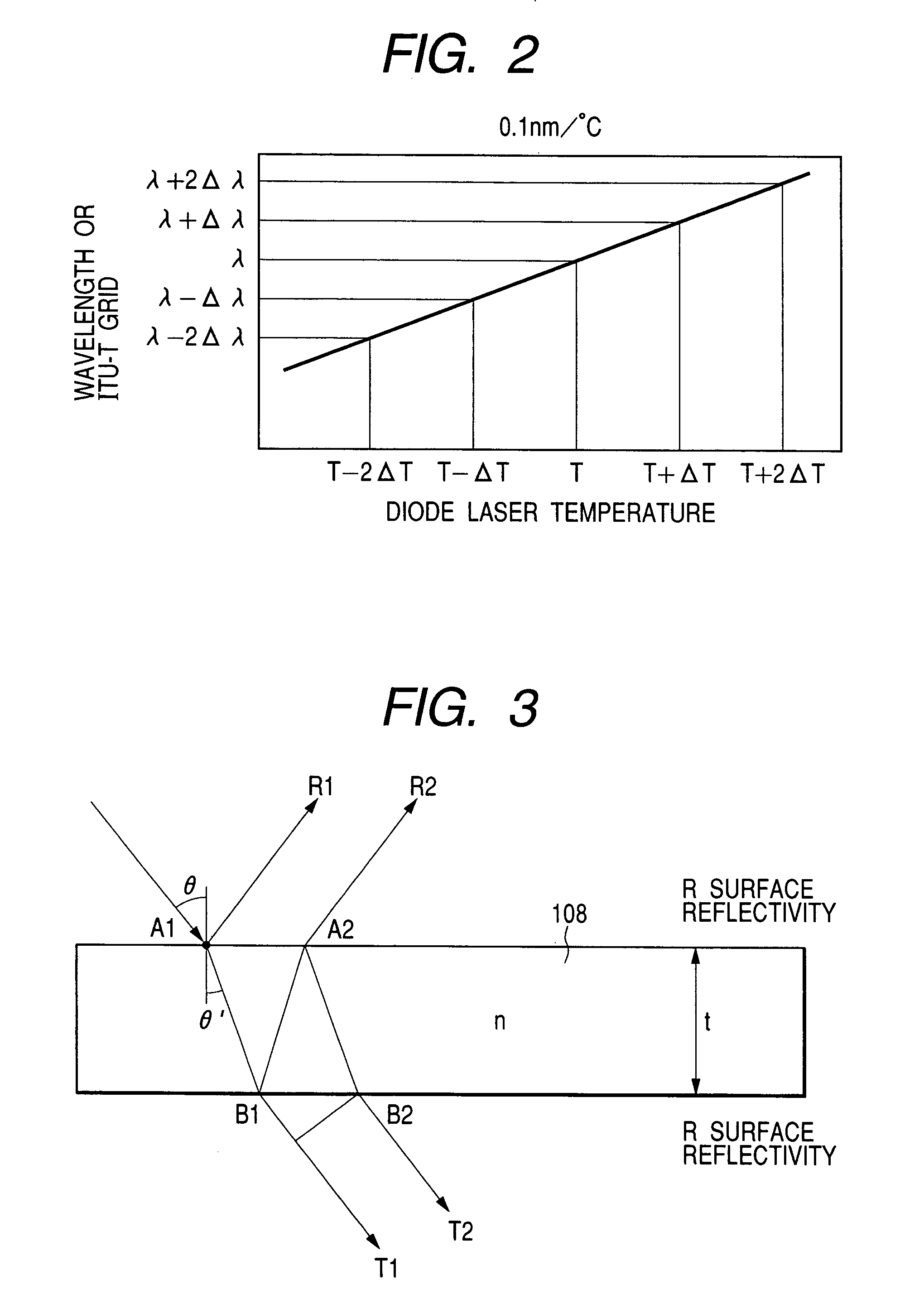
[0009]The following description provides typical examples of the construction of an optical cavity in which multi-interference between the above-mentioned laser diode device and the above-mentioned wavelength selective member is eliminated. The first scheme involves a technique in which the polarization directions of the light emitted from the light source and of light returning to the light source, as returned light, are made different from each other. A more concrete example is as follows. The above-mentioned wavelength selective member in an optical path between the laser diode and the above-mentioned wavelength selective member itself is arranged so as to generate reflected light having a degree of polarization different from that of the incident light falling on the wavelength selective member. In the most preferable form, this difference between the directions of polarization is such that the directions of polarization are mutually orthogonal, which can ensure the most stable operation.

Problems solved by technology

Thus, light that arrives at a photo detector fluctuates, thereby to generate a ripple in the output, and so there arises a problem of instability in this wavelength deviation signal.
That is, in the operation of a laser diode, there is the problem that so-called external feedback noise (returned light noise) is generated, namely a fluctuation in the lasing intensity resulting from contention of the lasing mode of the laser diode itself with an external resonance mode that is generated by light returned to the laser diode being coupled to a waveguide thereof.

Method used


Image

  • Laser diode module
  • Laser diode module
  • Laser diode module

Examples


Embodiment Construction

[0025]As can be understood from the foregoing description, in order to reduce multi-interference in the resonator that is formed between the facet of the laser diode and a wavelength deviation detection filter, a representative embodiment of the present invention adopts a configuration wherein the facet of the laser diode and a wavelength deviation detection filter are arranged so as not to be parallel with each other, or wherein, by arranging a wave plate inside the resonator, the polarization states of the light beams are controlled so as to reduce superposition of the light beams having the same polarization; and, the arrangement further includes means for preventing multiple reflection by use of a polarizing element. Hereafter, several forms by which the objects of the present invention can be carried out in practice will be described as examples.

[0026]FIG. 1 shows an example of a control loop that acts to carry out wavelength locking according to the present invention. That is,...


PUM


Abstract

A laser diode module includes a laser diode device, a first photo detector part for receiving, first divided light that is a first portion of light when at least one of light emissions of the laser diode device is divided into two portions of light each traveling a different optical path, a second photo detector part for receiving second divided light that is a second portion of light thus divided via at least a wavelength selective member, and a controller which controls the lasing wavelength of the laser diode device on the basis of outputs of the first and second photo detector parts. A beam splitter provided between the laser diode and the wavelength selective member divides light emitted from the laser diode into the first and second divided light and a quarter-wave plate is provided in an optical path between the beam splitter and the wavelength selective member.

Description

CROSS-REFERENCE TO RELATED APPLICATION[0001]This application is a continuation of Ser. No. 09 / 934,562, filed Aug. 23, 2001, now U.S. Pat. No. 6,597,712, the subject matter incorporated by reference herein.BACKGROUND OF THE INVENTION[0002]The present invention relates to an optical communication module that is applied to a wavelength division multiplexing optical communication system. That is, the invention provides a stable optical system for locking a lasing wavelength of light from a laser source and a control system for the optical system. This optical system can be separately operated as a wavelength locker module, but it also can be integrated into an optical communication module having a laser source.[0003]Optical fiber communication features a long transmission length, high speed and large capacity, and a strong immunity to electromagnetic noises; and, hence, a communication system that assures high reliability can be provided. Formerly, in such systems, light of a single wav...

Claims


Application Information

Patent Timeline
IPC IPC(8): H01S3/00G01J4/00H01S5/00H01S5/022H01S5/0687
CPCH01S5/0687H01S5/0064H01S5/0085H01S5/4012H01S5/02284H01S5/02216H01S5/02251
Inventor TATSUNO, KIMIOFURUICHI, HIROAKIKAWAMOTO, KAZUMIKUROGUCHI, KATSUMI
Owner OPNEXT JAPAN INC
Learn More