
Method and system for processing replicated transactions parallel in secondary server

Inactive Publication Date: 2005-12-20
SOLID INFORMATION TECH
View PDF14 Cites 93 Cited by
  • Summary
  • Abstract
  • Description
  • Claims
  • Application Information

AI Technical Summary

Benefits of technology

[0016]The advantage of the invention is to improve speed and performance allowing parallel operations in hot standby, recovery and propagated transactions. High performance is needed in environments where large number of write operations are run each second and parallel processing power of a multi-processing computer is needed to handle the transaction load. Parallel operation according to the invention would not block all hot standby operations in a secondary server in case of executing large operations like creating and index for a large table. Hence, these improvements increase system availability in database server environment.
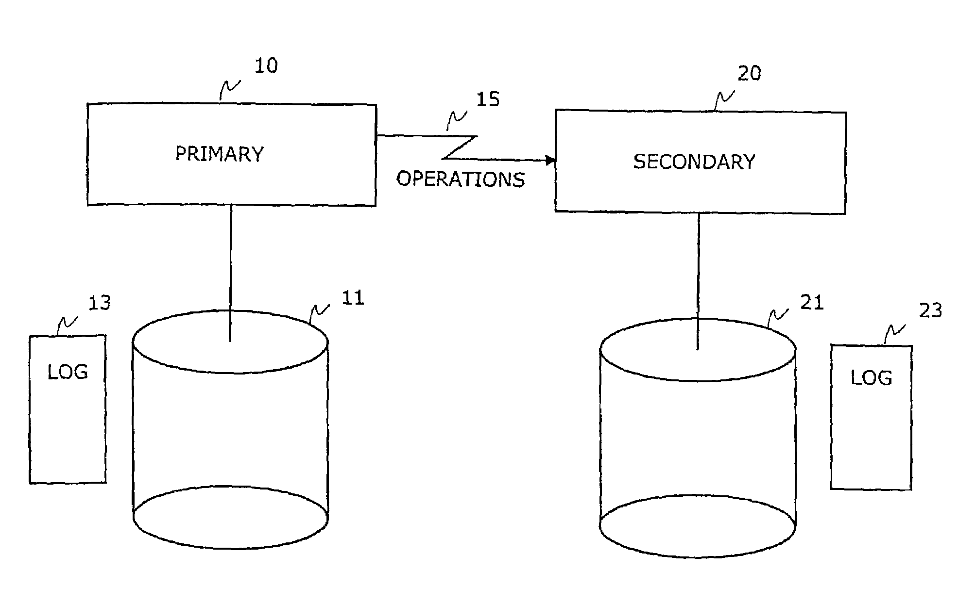
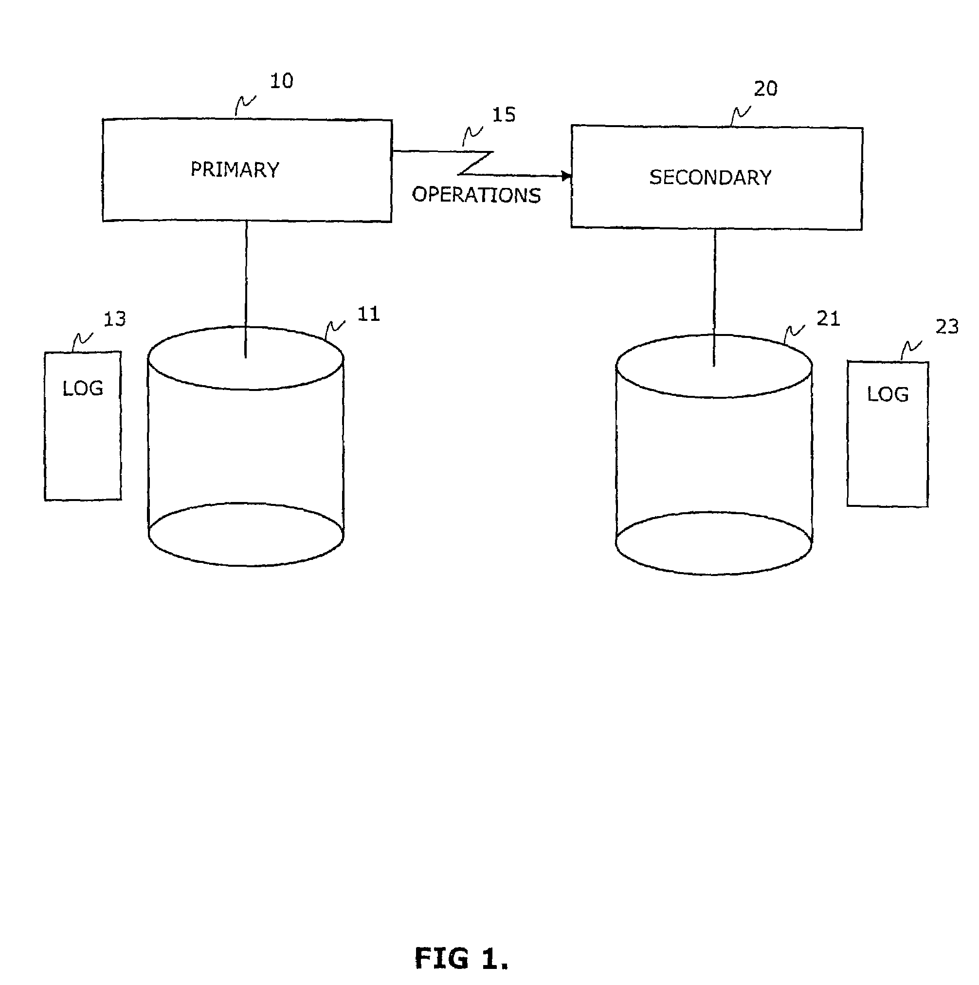
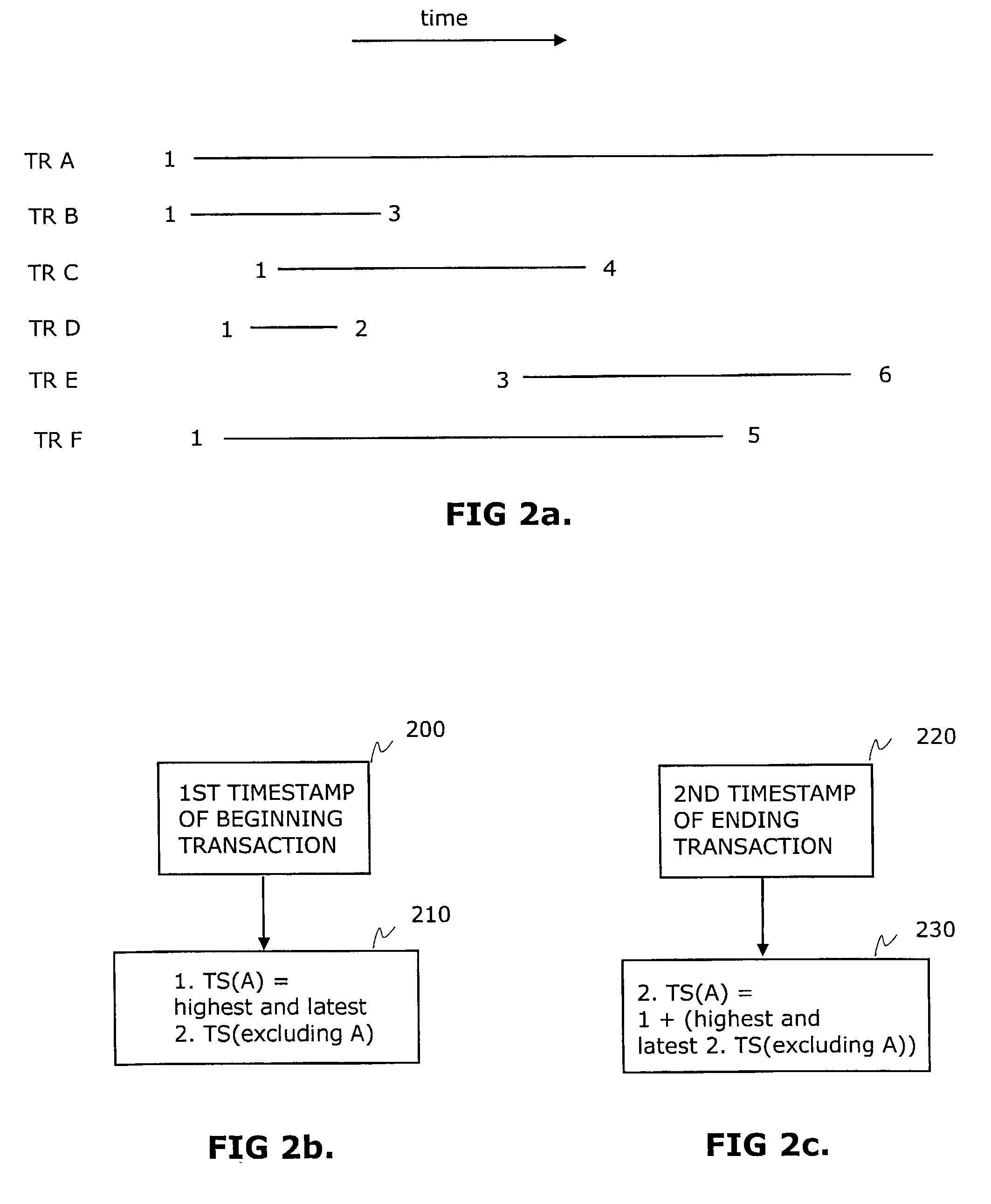
[0017]The best mode of the invention is considered to execute replicated hot standby transactions in the secondary server of a hot standby server pair in a parallel fashion whenever the transactions meet the timestamp-based criteria for parallel execution.
[0018]Some embodiments of the invention are described in the dependent claims.

Problems solved by technology

However, it requires lots of work from the application programmers as the application checkpointing mechanism is a difficult task to implement.
The replicated operations are run serially in the secondary node which slows down processing speed and hence reduces overall performance.
If the transaction fails in either of the databases, it needs to fail also in the other databases.
Using two-phase commit protocol needs to be done in the application which makes the application code more complex.
Moreover, distributed transactions are quite common cause to performance problems as the transaction cannot be completed before both databases acknowledge the transaction commit.
In this scenario, recovery from error situations can also be very difficult.
This method is not always suitable for real-time database mirroring because all transactions of the primary database may not yet be executed in the secondary database when the fail-over from primary to secondary happens.
However, in this scenario it is possible that a deadlock condition, where two transactions lock resources from each other, occurs and one of the transactions must be killed to clear the deadlock condition.
These concurrency control methods known in the prior art are suitable for use in the primary server of the Hot Standby database configuration to manage concurrent online transactions of client applications but they cannot be applied in the secondary server of the system.
This is because the concurrency conflict errors cannot be allowed in the secondary server as there is no way to properly handle these error conditions.
Because operations cannot be executed in parallel, it is difficult to improve secondary server's performance without raising problems in data integrity and transaction consistency.

Method used


Image

  • Method and system for processing replicated transactions parallel in secondary server
  • Method and system for processing replicated transactions parallel in secondary server
  • Method and system for processing replicated transactions parallel in secondary server

Examples


second embodiment

[0058]FIG. 5c illustrates a flow diagram of the invention when writing one transaction to the recovery log file 55. In step 500 transaction TR1(P) is beginning in the server that's operating in the normal mode. In next step 510 transaction TR1(P) issues commit operation C1(P) in the server. After this step, the server is killed and re-started in recovery mode 520. Next in step 530 the transaction is read from the recovery log, its begin information is send to PTE 540 and its timestamps are checked against the timestamp criteria 550: If there are no other recovery transactions that need to commit before the transaction start, transaction TR1(S) begins in the recovering server and write operations W1(S) are executed in the server according to step 560. After this commit operation C1(S) of transaction TR1(S) is read from the transaction log file, transmitted to PTE in step 570 and executed in the recovering server as depicted in step 580 after the second timestamp criteria evaluation p...

third embodiment

[0060]FIGS. 6a, 6b, 6c and 6d illustrate a method and system for executing a batch of earlier created transactions in a second database according to the invention. The transactions are created and executed in a first database in which they are also saved to a transaction queue for later, deferred execution in a second database. The transactions may be executed in the second database for example after a period of time has passed or when an application of the first database wants to send the transactions to the second database for example as part of asynchronous data replication process. The transactions of this batch may be for example Intelligent Transactions [2]. In connection with transactions and operations P in parenthesis means primary server side (first database) and S relates to secondary server side (second database) in this embodiment. In FIG. 6a transactions TR1(P), TR2(P) and TR3(P) from the first server are transmitted to the transaction queue that can be for example a s...


PUM


Abstract

This invention relates generally to database servers and computer systems and, more particularly, describes the mechanism to run transaction operations originating from a primary server used to replicate data in parallel in a secondary server. Especially the invention relates to running concurrent or parallel operations in a secondary server for redundancy, recovery and propagated transactions. This invention describes how parallel operation in a secondary server improves performance and availability and how it maintains transaction order and output congruent with the primary server where transaction operations are originated.

Description

TECHNICAL FIELD OF THE INVENTION[0001]The present invention relates generally to database server and computer systems and, more particularly, to run transaction operations in a fault tolerant system originating from a primary server used to replicate data in parallel in a secondary server. Especially the invention relates to running parallel transactions in a secondary server for redundancy or recovery purposes.BACKGROUND OF THE INVENTION[0002]Various mechanisms are known for replication or recovery of data in a database server system to ensure correct operation in the case of a crash of a system or a failure that causes the system to be out of order for an undefined period of time.[0003]A Hot Standby (HS) is a mechanism which supports non-disruptive failover of database server system maintaining system availability, i.e. its ability to provide desired service when required, by a second server system ready to take over when the main system is unavailable. In the hot standby replicat...

Claims


Application Information

Patent Timeline
IPC IPC(8): G06F7/00G06F11/00G06F17/30
CPCG06F11/1471G06F11/2023G06F11/2097G06F17/30353G06F11/2038G06F11/2048Y10S707/99953G06F2201/80G06F16/2322
Inventor RUUTH, JARMOPARKKINEN, JARMOSOINI, PETRIWOLSKI, ANTONI
Owner SOLID INFORMATION TECH
Learn More