
Apparatus for controlling retaining ring and wafer head tilt for chemical mechanical polishing

a technology of mechanical polishing and retaining ring, which is applied in the direction of grinding drive, grinding drive, grinding surface conditioning device, etc., can solve the problems of wave-like shape producing non-uniform profiles on the exposed surface of the wafer, affecting the etc., to achieve accurate measurement and facilitate repeatability of eccentric force measurements

Inactive Publication Date: 2005-12-20
LAM RES CORP
View PDF111 Cites 14 Cited by
  • Summary
  • Abstract
  • Description
  • Claims
  • Application Information

AI Technical Summary

Benefits of technology

The present invention provides systems and methods for measuring eccentric forces in CMP processes. The systems and methods allow for accurate measurements of forces applied to carriers, such as wafers or puck carriers, even if the force is applied eccentrically. The systems and methods also provide for supplying fluids to the carriers and wafers without interfering with the polishing operations. Additionally, the invention provides a vacuum chuck that can apply vacuum to the wafer uniformly and a puck support with perforations for distributing fluid. The technical effects of the invention include improved accuracy in measuring forces and efficient cleaning of carriers during polishing operations.

Problems solved by technology

Without planarization, fabrication of additional metallization layers becomes substantially more difficult due to the higher variations in the surface topography.
However, in some CMP systems, the polishing pads may contain fixed abrasive particles throughout their surfaces.
Several problems may be encountered while using a typical CMP system.
One recurring problem is called “edge-effect,” which is caused when the CMP system polishes an edge of the wafer at a different rate than other regions of the wafer.
The wave-like shape may produce non-uniform profiles on the exposed surface of the wafer.
The burn-off effect occurs when a sharper edge of the wafer is excessively polished as it makes contact with the surface of the polishing pad.
As a consequence of the burn-off effect, the edges of the resulting polished wafers exhibit a burn ring that renders the edge region unusable for fabricating silicon devices.
Another shortcoming of conventional CMP systems is an inability to polish the surface of the wafer along a desired finishing layer profile.
Thus, the surface of the pad polishes the finishing layer irrespective of the wavy profile of the finishing layer, thereby causing the thickness of the finishing layer to be non-uniform.
As may be understood from the above discussion of the edge-effects, pad rebound effects, and edge burn-off effects, it would be undesirable for such eccentric force to cause the central axes of the wafer and the carrier to depart from the initial orientation and to tilt, or assume a tilted orientation, under the action of the eccentric force.
However, in the eccentric force situation described above (i.e., when the area of the polishing pad, for example, does not totally overlap the area of the exposed surface of the wafer) such gimbals may not be used.
Further, with such large collar, frictional losses would be relatively large between the collar and the support holder, and may be variable as well.
However, vacuum applied through such holes can deform the wafer and interfere with the accuracy of polishing operations on the wafer on the metal backing.
Also, slurry used in the polishing operations can block one or more of the holes, and result in a false indication of wafer presence on the metal backing.
Another problem faced in providing preparation heads, such as wafer polishing heads, is that one head may be used to carry a particular wafer during many different processing steps (e.g., wafer polishing and buffing) Here, the carrier with the wafer attached, is first mounted at one processing station, and processed.

Method used


Image

  • Apparatus for controlling retaining ring and wafer head tilt for chemical mechanical polishing
  • Apparatus for controlling retaining ring and wafer head tilt for chemical mechanical polishing
  • Apparatus for controlling retaining ring and wafer head tilt for chemical mechanical polishing

Examples


Embodiment Construction

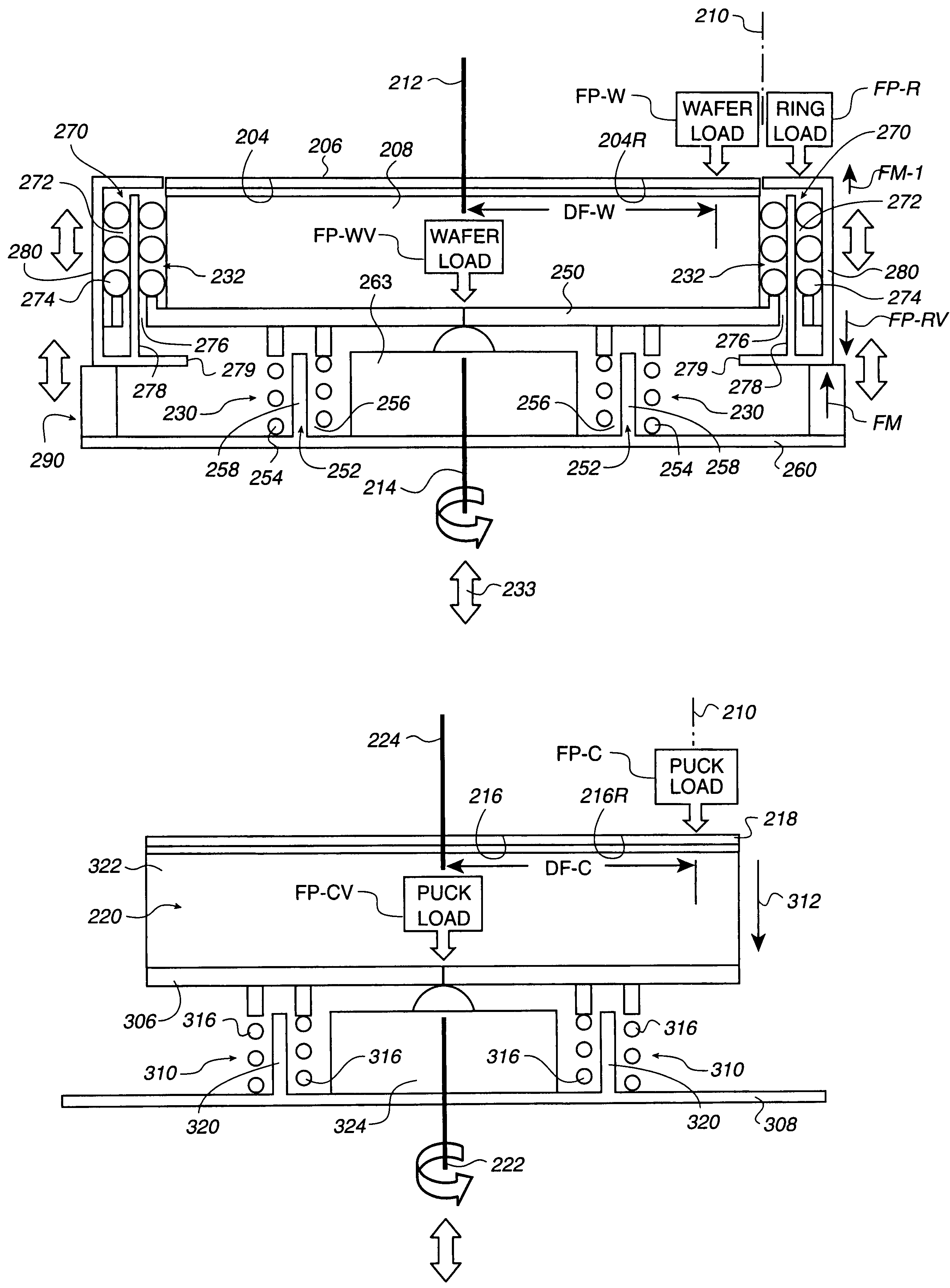
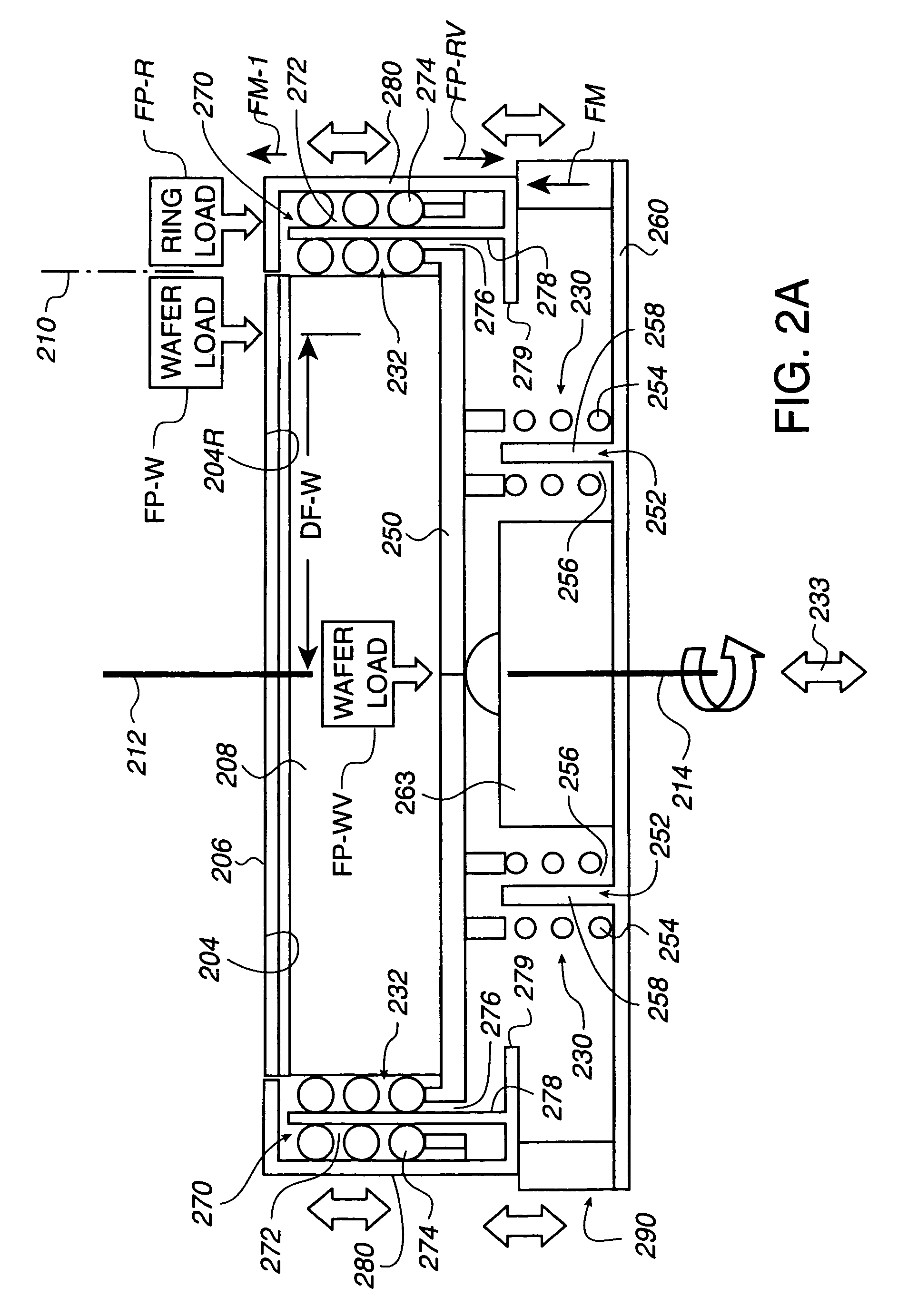
[0065]An invention is described for a CMP system, and methods, which enable precision controlled polishing of an exposed surface, which may include layer surfaces, of a wafer. The CMP system and methods substantially eliminate the aforementioned edge-effects, pad rebound effects, and edge burn-off effects, while structure and operations are provided that facilitate making repeatable measurements of the eccentric forces. In such CMP systems and methods, a force applied to a carrier, such as a wafer or puck carrier, may be accurately measured, as defined above, even though such force is eccentrically applied to such carrier. The CMP system and methods have the above-described repeatable measurement features, while providing facilities supplying fluids within a carrier to the wafer and a wafer support without interfering with the polishing operations. Similarly, the CMP system and methods remove fluids from the wafer or puck carrier without interfering with the CMP operations.

[0066]In ...


PUM

PropertyMeasurementUnit
diameteraaaaaaaaaa
diameteraaaaaaaaaa
angleaaaaaaaaaa

Abstract

A CMP system accurately measures eccentric forces applied to carriers for wafer or polishing pad conditioning pucks. An initial coaxial relationship between wafer axis of rotation and a carrier axis is maintained during application of the eccentric force, such that a sensor may measure the eccentric forces. Such initial coaxial relationship is maintained by a linear bearing assembly mounted between the carrier and the sensor. The linear bearing assembly is provided as an array of separate linear bearing assemblies, and may be assembled with a retainer ring in conjunction with a motor for moving the ring relative to the wafer mounted on the carrier so that an exposed surface of the wafer and a surface of the retainer ring to be engaged by the polishing pad are coplanar during the polishing operation.

Description

CROSS REFERENCE TO RELATED APPLICATION[0001]This application is a divisional application of application Ser. No. 09 / 668,667 filed Sep. 22, 2000 by Damon Vincent Williams and entitled Apparatus and Methods For Controlling Retaining Ring And Wafer Head Tilt For Chemical Mechanical Polishing (referred to as the “Parent Application”), now U.S. Pat. No. 6,652,357 issued Nov. 25, 2003. Priority under 35 USC 120 is claimed based on the Parent application Ser. No. 09 / 668,667. The disclosure of the Parent Application is incorporated by reference.FIELD OF THE INVENTION[0002]The present invention relates generally to chemical mechanical polishing (CMP) systems and techniques for improving the performance and effectiveness of CMP operations. Specifically, the present invention relates to carrier heads for wafers and pad conditioning pucks, in which repeatability is provided in measuring forces applied to the heads eccentrically of a main axis of the head are resisted, wherein the heads, with th...

Claims


Application Information

Patent Timeline
Patent Type & Authority Patents(United States)
IPC IPC(8): B24B41/04B24B41/06B24B49/16B24B53/007H01L21/306
CPCB24B41/04B24B41/061B24B49/16B24B53/017H01L21/30625
Inventor WILLIAMS, DAMON VINCENT
Owner LAM RES CORP
Learn More