Online bakeout of regenerative oxidizers

a technology of regenerative oxidizers and bakeouts, which is applied in the field of online bakeouts of regenerative oxidizers, can solve the problems of loss of regenerative oxidizer efficiency, or malfunction, loss of production time, and insufficient residence time of heated purge gas, etc., and achieves the effect of reducing the required bakeout time and reducing the bakeout tim

Active Publication Date: 2005-12-13
DURR SYST INC
View PDF5 Cites 9 Cited by
  • Summary
  • Abstract
  • Description
  • Claims
  • Application Information

AI Technical Summary

Benefits of technology

[0011]As will be understood by those skilled in this art, the purge gas may be directed downwardly or upwardly through the heat sink media of at least one segment or compartment depending upon the design of the regenerative oxidizer. In a downward purge, hot oxidized clean air from the combustion chamber is pulled downwardly through at least one segment, referred to herein as the third segment, to clean trapped dirty waste gas in the segment to enhance the destruction efficiency of the regenerative oxidizer. In the beginning, the downward purge gas is hot but as it travels down through the heat sink media, most of the heat is dissipated and the heat sink media and purge gases become ambient at the exit point. However, if sufficient time is allowed, the heat sink media in a pie-shaped segment can become saturated with heat allowing downward purge gases to become hot at the exit location, wherein accumulated matter is typically present, thus initiating bakeout.
[0020]Another preferred embodiment of this invention utilizes an auxiliary heat source, such as a burner, with an upward purge. In this embodiment, the regenerative oxidizer preferably includes a duct receiving heated clean gas from the outlet of the regenerative oxidizer directing clean gas to the stack or from the ambient atmosphere. This duct may include an auxiliary heater, such as a burner, which heats the gas, and the heated gas is then directed upwardly through the third and fourth sectors depending upon the design of the rotary valve. Thus, an elevated temperature of the purge gas can be achieved which is not a function of time. This method thus reduces the bakeout time of the accumulated particulate and condensable matter in the third and fourth sectors, thus reducing the required bakeout time. As will be understood, the fastest method of completing the bakeout would be an upward purge with an auxiliary burner wherein the heated purge gas is directed to both the third and fourth segments.
[0021]Thus, the method of cleaning the heat sink media of a regenerative oxidizer of this invention is relatively simple, can be electronically controlled and provides for continued cleaning of the waste gases through the regenerative oxidizer during the bakeout procedure.

Problems solved by technology

If the quantity of these fouling agents is sufficient, then the flow passages through the heat sink media can be compromised, causing loss of efficiency of the regenerative oxidizer, or malfunction.
This often implies down time for the process to which the regenerative oxidizer is applied and hence loss of production time.
However, testing of the bakeout process disclosed in this patent indicated that the residence time of the heated purge gas is insufficient to burn off accumulated non-volatile contaminants from the heat sink media using the method described in the above-referenced U.S. Pat. No. 6,203,316.
Further, it is not possible to simply hold the position of the rotary valve for a time sufficient for bakeout or burn-off of the accumulated non-volatile contaminants without compromising the efficiency of the rotary regenerative oxidizer, because it has been found that bakeout of the accumulated non-volatile contaminants takes between ten to ninety minutes or more preferably about fifty minutes.

Method used


Image

  • Online bakeout of regenerative oxidizers
  • Online bakeout of regenerative oxidizers
  • Online bakeout of regenerative oxidizers

Examples


Embodiment Construction

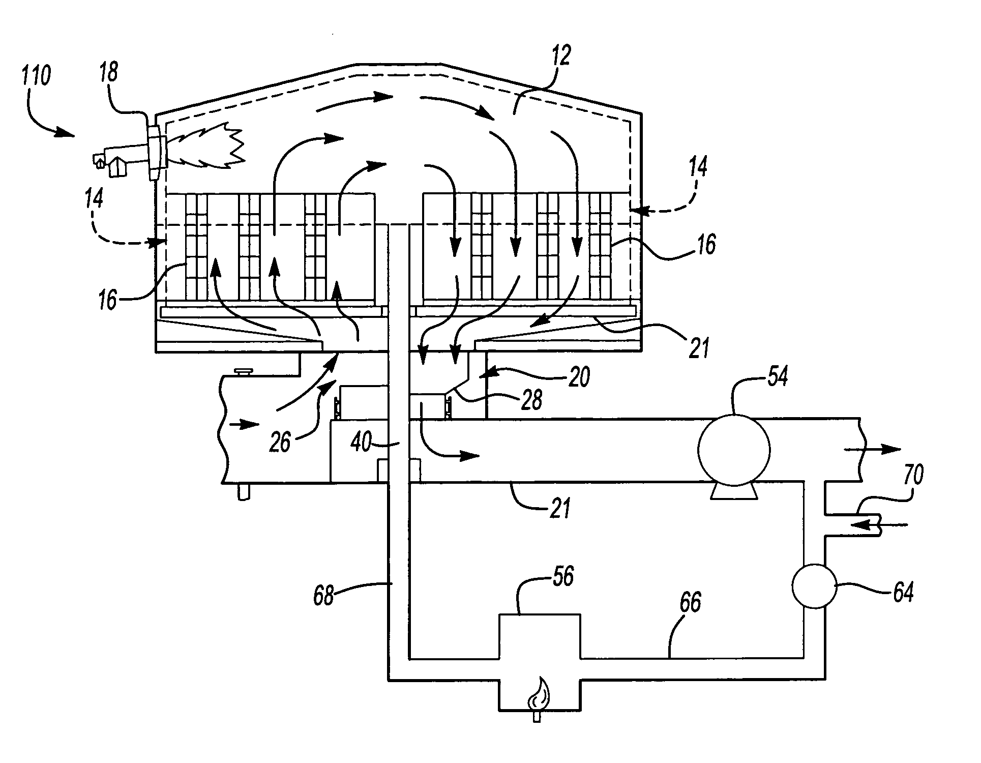
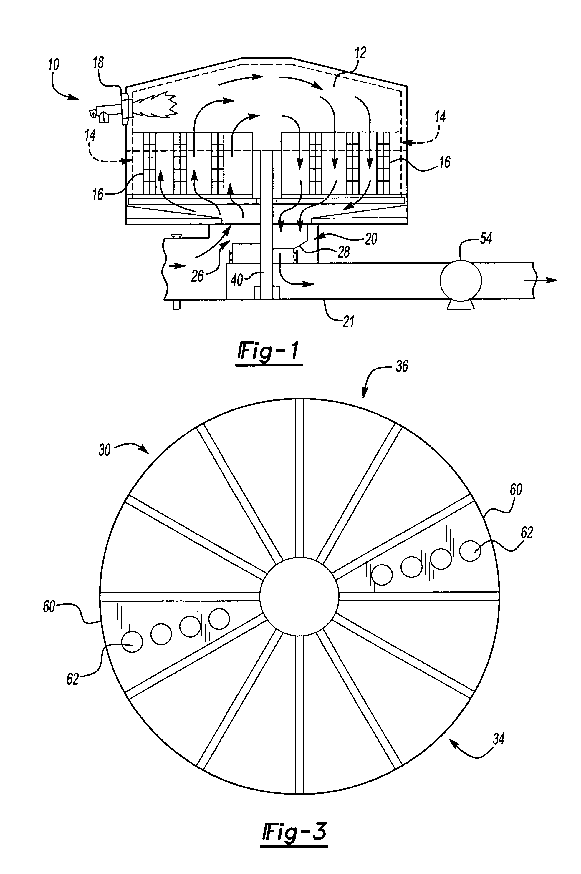
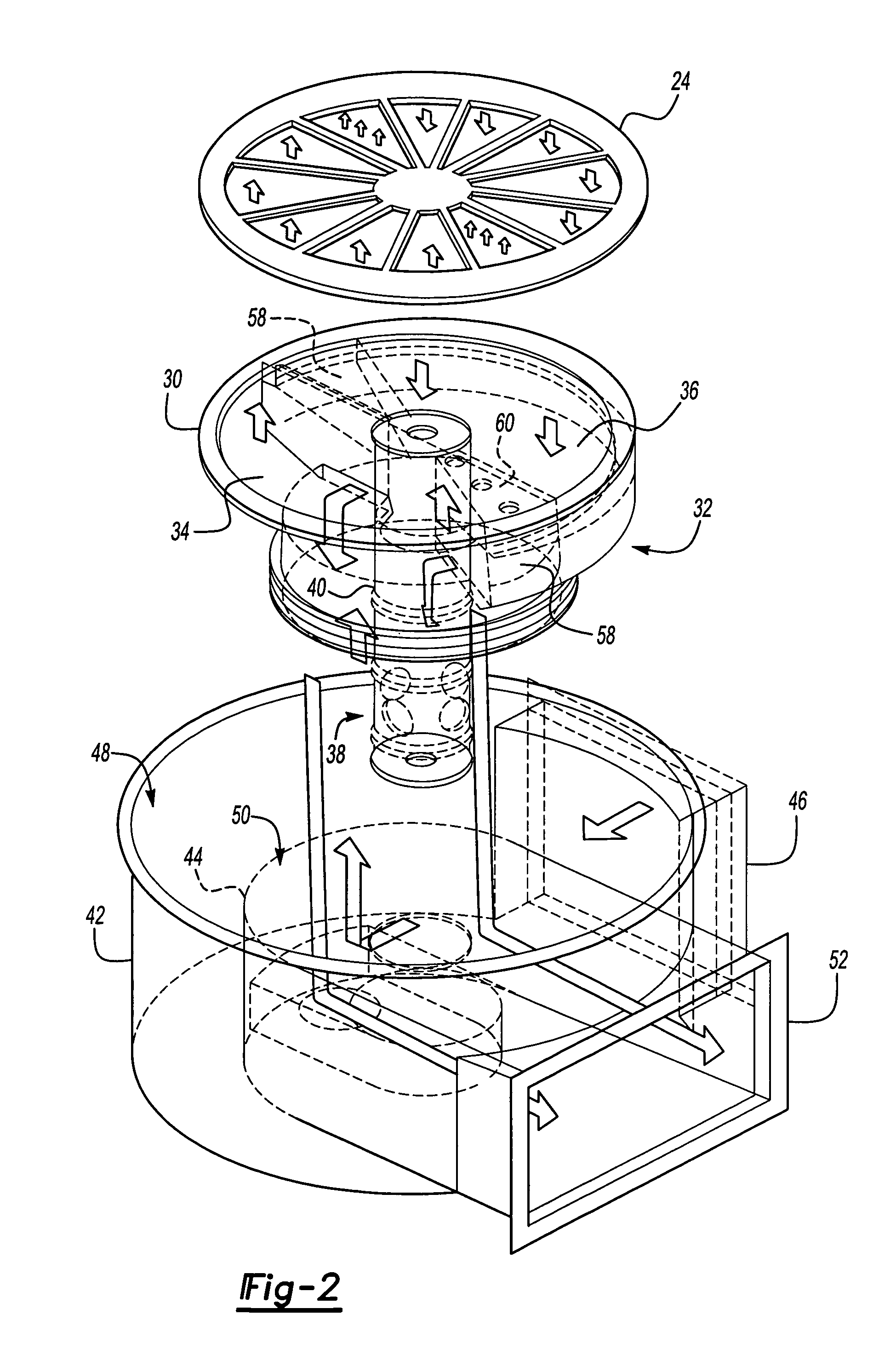
[0027]The rotary regenerative oxidizer 10 illustrated in FIG. 1 is generally conventional for illustrative purposes only and thus does not limit the method of cleaning the heat sink media of this invention, except as set forth in the appended claims. The illustrated rotary regenerative oxidizer 10 includes a combustion chamber 12, pie-shaped compartments or segments 14 each including heat sink media 16 therein as described above. A burner 18 heats the gas in the combustion chamber 12 to a temperature sufficient to oxidize the volatile organic compounds received therein, typically to a temperature generally about 600° F. The pie-shaped compartments or segments 14 are open at both ends to communicate with the combustion chamber 12 at one end and the rotary valve 20 at the other end, the components of which are shown in detail in FIG. 2. A stator 24 is located between the rotary valve 20 and the lower open ends of the pie-shaped compartments 14 shown in FIG. 2.

[0028]The waste gas strea...


PUM


Abstract

A method of burning off accumulated contaminants from heat sink media of a regenerative oxidizer having a plurality of segments containing media arranged around a central axis and a rotary valve which includes repeatedly rotating the rotary valve 180 degrees to alternatively direct waste gas through a first plurality of segments, direct the hot gas through a second plurality of segments and purge gas through a third segment to burn off the contaminants, then indexing the rotary valve one segment and repeating the burn-off process of all segments.

Description

FIELD OF THE INVENTION[0001]This invention relates to an improved method of cleaning and removing accumulated particulate and condensable matter from the media or heat sink of regenerative oxidizers by burning or banking off the deposited matter without interrupting processing of waste gases through the oxidizer. That is, the regenerative oxidizer continues online operation without interruption during the bakeout procedure.BACKGROUND OF THE INVENTION[0002]Regenerative oxidizers (RO), including regenerative thermal oxidizers (RTO) and regenerative catalytic oxidizers (RCO), use a large mass of media or heat sink, usually ceramic based, to provide a high degree of recovery. Typically, the heat sink media of a regenerative oxidizer is in the form of saddles, glued laminated sheets or extruded honeycomb monoliths. Because of the economic benefits of regenerative oxidizers, a large number of polluted gaseous streams are abated by regenerative oxidizers. In some applications, in addition ...

Claims


Application Information

Patent Timeline
Patent Type & Authority Patents(United States)
IPC IPC(8): F23G7/06F23J1/00F23J3/02F27D17/00F28G11/00
CPCF23G7/068F23J3/02F27D17/004F27D17/008F28G11/00
Inventor AHN, SUNJUNGMCANESPIE, DONALD I.SCHROEDER, JASON T.
Owner DURR SYST INC
Why Eureka
Try Eureka