
Right side universal electrocardiogram sensor positioning mask and method

a technology of universal electrocardiogram and positioning mask, which is applied in the field of dermal chest masks, can solve the problems of high cost, time-consuming, and difficult accuracy of lead placement and attachment, and achieve the effects of less time, simplified sales and distribution, and high volume production

Inactive Publication Date: 2005-12-06
UNILEAD INT
View PDF2 Cites 40 Cited by
  • Summary
  • Abstract
  • Description
  • Claims
  • Application Information

AI Technical Summary

Benefits of technology

[0032]It is another object of the present invention to provide a universal ECG multiple sensor positioning device whereby one size fits all including extra large rather than requiring a multitude of different sizes thereby achieving economic benefits of high volume production and simplified sales and distribution.
[0034]It is still another object of the present invention to provide a universal ECG sensor mask and method of use in which simplified, efficacious, and repeatable sensor placement results on either the left or right side of a human chest are guaranteed.

Problems solved by technology

However, accurate placement and attachment of a large number of leads can be difficult and time consuming and requires knowledge, skill, and diligence on the part of the person attaching the electrodes or sensors.
Mechanical problems in attaching multiple leads to a patient range from tangling of lead wires, and excessive time consumed in pairing lead wires with the appropriate electrodes, to difficulty in locating anatomical landmarks on a patient with precision.
Problems occur if the leads are not properly placed and are located higher or lower than optimal.
Research reported in the electrocardiography literature indicates that precordial leads placed one inch or more from their true anatomical landmarks can result in misinterpretation of the patient's ECG.
This may result in or contribute to diagnosis errors, false hospital admissions, sending sick people home, or have other negative impacts on diagnosis or treatment.
The placement problem is compounded when serial comparisons are made between two or more ECGs taken over time.
However, in busy clinical environments or emergency situations, medical personnel are often so rushed they may not even palpate the patient.
Under those conditions, precordial leads are commonly placed with inadequate palpation and with little attention to a patient's particular anatomy.
In addition, training and maintaining the necessary skill for proper placement of individual leads is time and resource consuming and often not adequate.
Electrode V3 is most often misplaced too low.
The most obvious conclusion to be drawn is that lead placement is often not accurate.
This is a time consuming operation which increases the risk in an emergency situation.
Crossed lead wires are a more significant problem when the ECG monitor does not provide interpretation of the recordings and cannot alert the operator of this possibility.
Accordingly, critical time can be lost both in the removal of the chest leads of the ECG test equipment in order to administer aid to a patient and in their subsequent replacement after aid has been administered.
The basic problem with all of these inventions is that they require multiple sizes of sensor positioning masks to fit various sized persons.
Thus, Manoli does not describe how to size a patient, and it is common for persons placing individual electrodes to make errors.
If similar errors are made when sizing the patient for Manoli's device, it is quite likely that the wrong size device would be selected.
This trial and error approach wastes time and materials since the first device would need to be discarded without ever being used to take an ECG.
Such a determination is time consuming and would at least be impeded by the fact that palpation will be difficult to perform once the sheet is placed over a patient's chest.
Moreover, each group of electrodes provides a source for error since there are three electrodes to choose from in each group.
Stratbucker relies on a judgment determination for each group of electrodes and therefore selection is time consuming and inexact due to the device physically covering the patient's anatomical features.
Not only does this allow for error, it also reduces the chances of consistent electrode placement from one test to the next, thereby confounding any serial comparisons between tests.
It also increases the length of time to administer a resting ECG since a separate decision must be made for each group of electrodes.

Method used


Image

  • Right side universal electrocardiogram sensor positioning mask and method
  • Right side universal electrocardiogram sensor positioning mask and method
  • Right side universal electrocardiogram sensor positioning mask and method

Examples


Embodiment Construction

[0044]Reference is made to the drawings for a description of the preferred embodiment of the present invention wherein like reference numbers represent like elements on corresponding views.

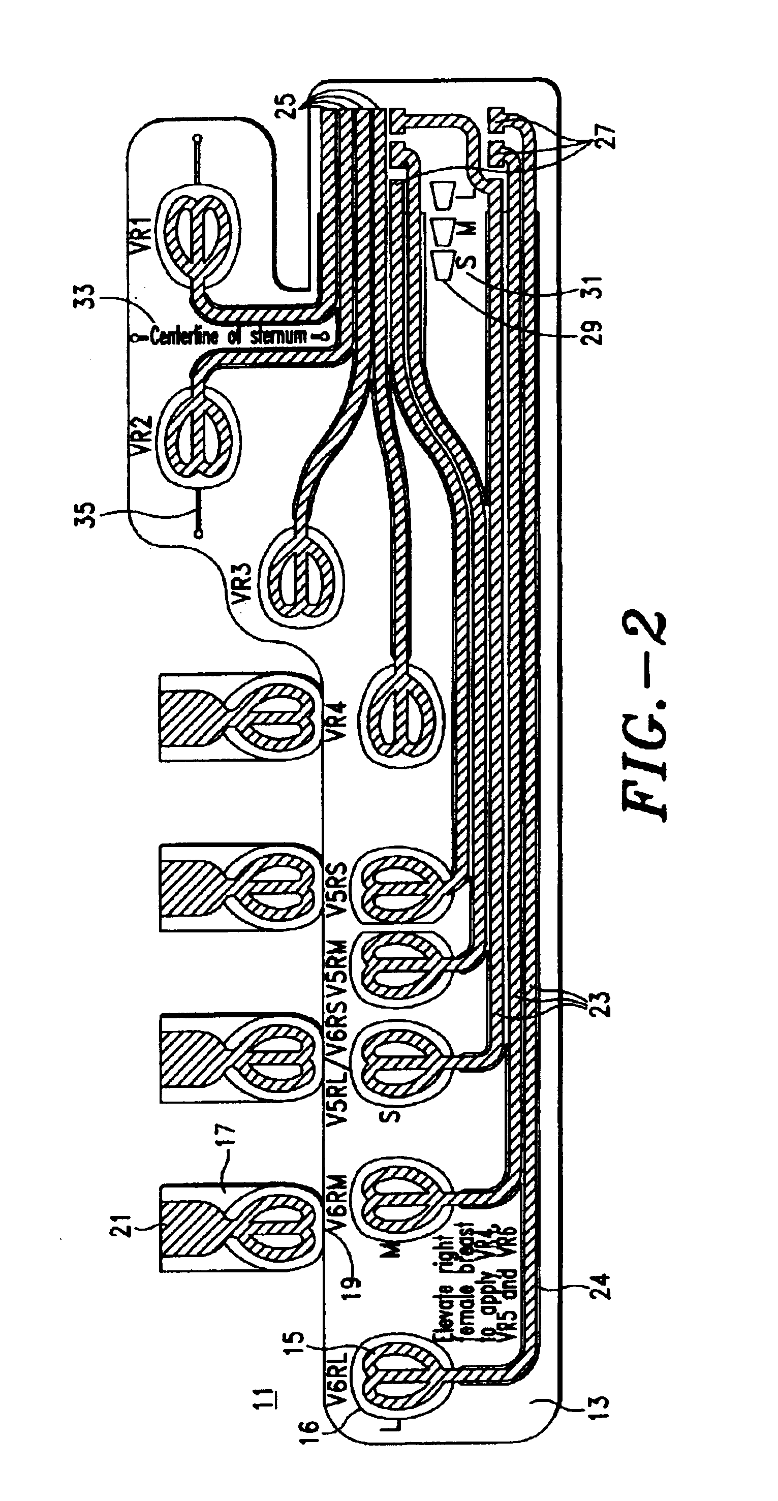
[0045]FIG. 1 illustrates a plan view of the universal disposable ECG sensor positioning mask of the present invention for three sizes of human torso for placement on the left chest of a patient for performing an ECG test. FIG. 2 illustrates a plan view of the opposite side of the universal disposable ECG sensor positioning mask of FIG. 1 for placement on the right chest of a patient for performing a right chest ECG test. FIG. 3 illustrates a plan view of the universal disposable ECG sensor positioning mask of the present invention for four sizes of human torso including extra large for placement on the left chest of a patient for performing an ECG test. FIG. 4 illustrates a plan view of the opposite side of the universal disposable ECG sensor positioning mask of FIG. 3 for placement on the right c...


PUM


Abstract

A universal and reversible disposable ECG sensor positioning mask and method for use with electrocardiogram diagnostic equipment for left and right chest ECGs in which the mask has at least nine sensors, six of which can be used at any one time to provide up to four different sizes to accommodate varying sized human torsos.

Description

RELATED APPLICATIONS[0001]This is a continuation-in-part of U.S. patent application Ser. No. 10 / 021,937, filed on Dec. 13, 2001, now U.S. Pat. No. 6,553,246, issued Apr. 22, 2003, for a Universal Electrocardiogram Sensor Positioning Device and Method which is a continuation-in-part of U.S. patent application Ser. No. 09 / 461,701, filed on Dec. 14, 1999, now U.S. Pat. No. 6,400,977 BI, issued Jun. 4, 2002, for A Universal Electrocardiogram Sensor Positioning Device and Method, which is a continuation of U.S. patent application Ser. No. 09 / 022,730, filed on Feb. 12, 1998, now U.S. Pat. No. 6,006,125, issued Dec. 21, 1999.BACKGROUND OF THE INVENTION[0002]1. Field of the Invention[0003]The present invention relates to a disposable dermal chest mask for assistance in establishing electrical communication between sensors on a human chest and electrocardiograph machines. More particularly, it relates to a universal electrocardiogram sensor positioning mask and method for the right side of h...

Claims


Application Information

Patent Timeline
Patent Type & Authority Patents(United States)
IPC IPC(8): A61B5/0402A61B5/0408
CPCA61B5/04085A61B5/6841A61B5/282
Inventor WENGER, WILLIAM K.
Owner UNILEAD INT
Learn More